Weird sensor connection

theripley

Member
Join Date
Jul 2008
Location
laguna
Posts
545
Hi

I have attached files.

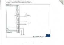
On page 1, PT are temperature sensors connected to various tanks, RT13-16 are single contact relays and B110-11F are PLC addresses (FUJI PLC output module NC1Y32T05P1).

As observed PT 1A-6A their leads shorted altogether. So are PT 7A-12A, PT 1B-6B, PT 7B-12B & PT 1C-6C, PT 7C- 12C. They are now compressed to A1 (PT 1A-7A), A2 (PT 7A-12A), B1 (PT 1B-6B), B2 (PT 7B-12B), C1( PT 1C-6C), C2 (PT 7C-12C).

These are now connected to (see page 2) the temp. module unit NC1AX02-PT (which unfortunately I cannot find a manual).

I do not understand this connection. Can somebody please help me analyze.

Erika
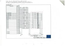
ripley_Page_1.jpg ripley_Page_2.jpg
 
Looks like simple multiplexing to me. They use the relays to select which thermocouple shows up on the analog input.

🍻

-Eric
 
Do you mean that temperature reading of these sensors are not simultaneous? Rather, reading is chosen 1 @ a time. Is this safe? This is the first time I have encountered such.
 
Why is there a need to multiplex sensor?

Analog inputs are not much different in price per point today than they were 20 or more years ago so you can see that back then they were expensive which is why they were common back then

What are pros & cons? What are needed to be consider with this connection?

If they were well implemented and read reliably, they are often quite good at doing there job, but they can be more noisy than a single probe on a single input, they also are no use for real time right now use such as a PID loops, or where there are quick temperature changes that need quick responses.

If all works well then leave as is till such time as you do a PLC update then consider any change then.
 
PRO: Mux'ing RTD's works well, as shown, by switching only the one side (leg) of the resistance element. The analog input's source current flows through the resistance element, and the 3rd does its compensation thing, it's a clean measurement. Maybe a touch of error added by the resistance of the contacts.

CON: However, Mux'ing only one leg does not work with thermocouples. To Mux a thermocouple sensor, both legs of the same thermocouple need to be switched with double pole contacts.

I've run into grain storage bins where the analog inputs getting the output of the mux were voltage only inputs, not thermocouple inputs with cold junction (CJ) compensation, so there was CJ error on the order of 10s of degrees. A manual correction from a (ambient temp of thermometer in the panel minus freezing point of water) table was supposed to suffice. But no one ever made the correction because no one understood what it was for or felt the need to.
 
danw you are wrong with the RTD as you see the compensation wire stays connected so length is not compensated.
RIP this setting does work for thermocouples, however the relays will generate a too big error on the signal (it is only microvolts to measure).
Thermocouples can not be multiplexed this way as the error will be too big and changing all the time.
For RTD it can work with two or better with three contacts.
with two the compensation is not complete but is separated from each other and with three if there is a difference in contact resistance you will see it.
with four wires no problem to switch,.
 
The RTDs are 3 wire. The wires are labeded xA, xB, and xC, where x is 1 through 6 or 7 through 12.

xB and xC connect the return side (arbitrarily B) and the compensating leg (arbitrarily C) of each element to the RTD analog input terminals.

xA is each element's connection switched through the relay multiplexor.

Since both xB and xC are connected, I'd say it's a valid 3 wire RTD measurement with a compensating leg. The compensation leg can not compensate for any error due to contact resistance or wiring length difference between the A leg and B/C legs.
 
RTD is 3 wire correct, however the compensating (C) is connected to another RTD and its B leg so you will have 7 compensating wires in parallel, so measurement is wrong.

And when done correctly so with A and C both via relais and assuming the length of the wires is same compensation is correct.
To be fully correct the contact should also be in the B line but that may be a contact that is always closed.
readvalue is reading A - 2*reading C

Only one way to do this with one contact and that is with bridge wheatstone (old never done anymore.)
 
Now, I am confuse with this part of the program, see attached doc file.

This line allows scaling of the ch-1 analog input (WB13). It is then multiplied to a value of W30.0021. I have searched the origin of W30 but it is not used anywhere else in the program. Also I have searched on the touchscreen graphics but to no avail.

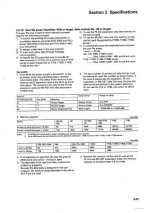
I have read the manual of the PLC CPU (FUJI F70), but I cannot understand what does W30 means (please see attached jpg file). Adding to my misery is the fact that the analog module is obsolete, so I could not find any manual.

Can somebody help me understand what does W30 means & when is it used?

fuji-0007.jpg
 

Attachments

  • Doc1.doc
    87 KB · Views: 5

Similar Topics

I have created a project in TIA Portal v16 Upd6 with S7-1200 (6ES7214-1AG40-0XB0) and WinCC Unified (PC station). The communication between the...
Replies
4
Views
135
I currently have a weird issue involving Ethernet IP communication between a ABB CI873 (EthernetIP Module) and a 1756-L83ES. The Layout is as...
Replies
8
Views
745
Good morning. I'm doing a rehab and I need to recycle some part of the old code that won't change and that I need. This is a calculation that...
Replies
22
Views
1,357
I'm trying to figure out a weird behavior I'm seeing in my CCW program. It's for controlling a gas polarizer (for medical imaging). I'm using an...
Replies
6
Views
459
I'm trying to figure out some weird behavior I'm seeing in one of my programs. This should be fairly straightforward - except that it's not...
Replies
11
Views
944
Back
Top Bottom