FTView Alarm Setup Question......

JoseM

Member
Join Date
Jul 2011
Location
Texas
Posts
381
I got this Logix PLC system that when an alarm is present, sets a 1 on this register N108[16].0 thru 13.

This PLC is talking to an HMI via Ethernet IP using Factory Talk View to display the alarms. The strange thing is that when I go to the "Alarm Setup" under FTView, they have alarms set in what it looks like an array that is associated to N108[16].

What got me confuse is that the array on FTView, is program to be trigger by the register N108[16].1 thru 14. There are individual messages for everyone of the bits 1 thru 14.

So, in other words, when the Logix PLC sets N108[16].0 to a logic 1, the message that gets display on the HMI is the one associated in the array to N108[16].1. I'm saying this because I had a situation where I couldn't reset an alarm and I found that N108[16].0 on the Logix PLC was triggering the alarm on array value N108[16].1 at the FTView HMI. How can this be?

Also, whoever program this system didn't consider that ones you set a register like N108[16].0 to a logic 1 due to a faulty condition, it won't go back to Zero (0) unless a logic 0 is force into the register bit, in other words, the alarm will never go away unless there is a way to put a logic 0 back into the N108[16] register ones all fault conditions are clear.
 
Last edited:
FT looks for a transition from zero to a non zero value to trigger the alarm, so even when using the bit trigger type you can't have a trigger value of zero. So they offset the bits by 1. HMI alarm bit 1 = N108[16].0, HMI alarm bit 2 = N108[16].1
 
I got this Logix PLC system that when an alarm is present, sets a 1 on this register N108[16].0 thru 13.

This PLC is talking to an HMI via Ethernet IP using Factory Talk View to display the alarms. The strange thing is that when I go to the "Alarm Setup" under FTView, they have alarms set in what it looks like an array that is associated to N108[16].

What got me confuse is that the array on FTView, is program to be trigger by the register N108[16].1 thru 14. There are individual messages for everyone of the bits 1 thru 14.

So, in other words, when the Logix PLC sets N108[16].0 to a logic 1, the message that gets display on the HMI is the one associated in the array to N108[16].1. I'm saying this because I had a situation where I couldn't reset an alarm and I found that N108[16].0 on the Logix PLC was triggering the alarm on array value N108[16].1 at the FTView HMI. How can this be?

Also, whoever program this system didn't consider that ones you set a register like N108[16].0 to a logic 1 due to a faulty condition, it won't go back to Zero (0) unless a logic 0 is force into the register bit, in other words, the alarm will never go away unless there is a way to put a logic 0 back into the N108[16] register ones all fault conditions are clear.

This is the way Rockwell has been implementing HMI applications alarms since forever; it's unintuitive, however, you'll eventually get used to it.
OTL the active alarm tag bit through a NC BOOL tag "connected" to the "Acknowledge Alarm" momentarily push button of your FTVS application.
When the alarm conditions are removed, "depressing" the Acknowledge Alarm button will "unlatch" the alarm bit OTL.
 
dmfrey, Let me see if I get this right, FTView looks at the array created for the alarm triggers,(eg. N108[16].1 - 14) and match them in numerical order to the signals given by the Logix plc through N108[16].0 - 13

N108[16].0 -------- N108[16].1 (Alarm 1)
N108[16].1 -------- N108[16].2 (Alarm 2)
N108[16].2 -------- N108[16].3 (Alarm 3)
N108[16].3 -------- N108[16].4 (Alarm 4)
N108[16].4 -------- N108[16].5 (Alarm 5)

The N108 tag on the Logix PLC goes from bit 0 thru 15 and by default FTView for the alarm setup goes from 1 thru 16 respectively.

Dmargineau, I kept pressing the button that the OEM created on the screen called "Clear" to acknowledge the alarm but the message wouldn't clear from the HMI. I had to go the Logix PLC and change the value of N108[16].0 which was set to 1 manually to 0 in order for the alarm to go away.

Do you have the HMI development software FactoryTalk View Studio ME and the runtime application file?
The "Clear" button has to be be "connected" to a RSL5K Tag which, upon written to by the HMI terminal, should clear the alarm bit within your Logix application.
Lookup your ladder logic, locate the alarm OTE (OTL) and verify the rung conditions in; somewhere there you should find the "reset" tag related to the HMI "Clear Alarm" button.
 
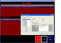
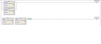
Here are two pictures of the FTView runtime application, specifically the "Alarm" screen and the RS5K code that show the "Alarm Acknowledge" link between the two.

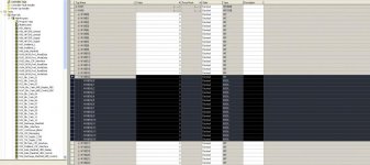
Also another picture that shows the RS5K controller tags screen showing the N108[16] register where you can see the N108[16].0 with a logic value of 1. Even after pressing the "Clear Alarm" button, the value on the register mention stay as 1 causing the alarm to be "ON" indefinitely.

FTV Alarm Screen.jpg RS5K_Alarm ACK.jpg N108 Register View.jpg
 
Last edited:
Pick the Messages tab of the FTVS Alarm Configuration utility and find the stack position of the active alarm message; each message is individually triggered by one of the bits of the Alarm Trigger words.
Then, within the RSL5K online project file, located the corresponding OTL of the tag triggering the message. It is going to be "true" and maintained in this state by the N102[15].4 "reset" tag.
There are quite a few trigger words, make sure you are highlighting them individually, one by one, and search for the messages attached to each one of them.
The "reset" mechanism should be identical to every configured alarm; it shouldn't be too hard to find the reason why one of them cannot be reset.
 
The "Trigger Value" on the FTV Alarm Setup, doesn't represent the numerical value we need to put on word N108[16] in order to trigger that respective alarm message but the bit level of the word N108[16] which every alarm message is linked too on that word, correct.
 
The "Trigger Value" on the FTV Alarm Setup, doesn't represent the numerical value we need to put on word N108[16] in order to trigger that respective alarm message but the bit level of the word N108[16] which every alarm message is linked too on that word, correct.

Yes, because your trigger type is set to "bit"
 

Similar Topics

I'd just like to confirm this works, if I could. In my project, I have 4 Alarm DINTs that I'm using for triggers at the bit level. If I set up...
Replies
6
Views
3,064
Is there a simple way (VBA or macro language) to acknowledge ONLY the most recent alarm? I upgraded recently all the way from RSVIEW 32 7.60 to...
Replies
4
Views
676
Hello all. Is there a way to upload alarm tags at the bit level to my FTView studio? I export them from my PLC thinking I will upload them to...
Replies
2
Views
408
Hi. I'm working on a project with FTView SE 13. What would be the easiest way to beep a sound as a new alarm appear on the banner?
Replies
2
Views
1,069
Hello experts! Can you guide me, please, step by step how to log alarm in my scada project to Ms sql server database. In my project there is some...
Replies
2
Views
1,358
Back
Top Bottom