Program Help

AutoNub

Member
Join Date
Oct 2011
Location
USA
Posts
11
Hello,

I've used PLCs in the past to perform very basic ladder logic, but I've never used one for a 4-20 mA output to drive a pump before. My pump takes a 4-20 mA signal to adjust the flow rate, but I need the Allen Bradley Micrologix 1200 (model L40BWA series C) with the analog module 1762-IF20F2 to creat the 4-20 mA output to the pump.

I'm having a little difficulty figuring out how to get the 4-20mA output. I have 24Vdc powering my PLC, and wires connected from out 8 and out 9 to the analog module at terminals IN 0 (+) and IN 0 (-). I'm not sure yet but I think this wiring is correct... although the outputs of the PLC might not matter (the 1762-IF20F2 instruction file says the 4-20mA corresponds to bits 8 and 9, but I don't recall if there's any correlation between the bits and the actual terminals).

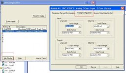
I believe the thing I'm missing here is the actual code necessary to give 4-20 mA control. I'm aware of the PID function, but I've never used it before. I'm not sure I should use it here because under Module Adv Config for a Data Format I've selected "Raw/Proportional" rather than "Scaled for PID."

If someone could show me the code or instructions necessary to create a 4-20 mA output it would be very much appreciate. I believe I need to vary a 0-10V output from the PLC to the analog expansion module so the module can in turn output a proportional 4-20 mA signal to the pump. Please correct me if I'm wrong and if possible, explain how I can achieve this goal.

Thank you in advance for your assistance.
 
1. Disconnect those wires, you haven't referenced inputs so don't worry about these.

2. Assuming you are using the first output wire "I Out 0" to the + side of your load. Wire the - side of your load to "COM"

3. The manual shows how to use the RSLogix 500 program to get the module input and output choices set up correctly (though they show the screen for a different module). This will set up those bits, including the bits '8' and '9' you mentioned.

4. Your outputs will be set by sending a number (0 - 32760 if in 'Raw/Proportional' format or 0 - 16380 if in 'Scaled For PID' format) though in each you get 4096 steps with a different amount of space (8 or 4 respectively) between numbers that make any change.

3. Let's say, for example, your analog module is the second add-on card. The outputs will be O2:0 and O2:1 respectively. To send minimum current (4 ma) send a 0 (zero) to O:2.0 (one command could be MOV 0 L:2.0). To send the maximum current (20 ma) send the maximum number discussed in #4 to the output address. To send a middle current (12 ma) send half of the maximum number.
 
Let me discuss the philosophy of a PID loop for a moment.

Let's say you know in advance that sending current 'X' will achieve precisely the effect you want. In that case a PID loop is not necessary.

But let's take a heating function for example. Sending 'X' amount of current may turn on a heating element to a precise amount but, in the end, you are trying to control the temperature of something. The final temperature may depend on a lot of things, the amount of stuff you are heating, outside air coming in or hot air going out, the outside temperature, lots of things. A PID loop uses information returned by a precisely chosen feedback devices, in this case some type of temperature measuring device, to report on the success of the function. The PID loop modifies the current output such that, after the system is 'tuned' properly, the system is brought to temperature rapidly then held there as needed without significant fluctuations. This is even with the variances noted before.

You may have a system where the final effect of a specific output is known precisely. Then great, you don't need a PID loop in the PLC (though I bet a PID loop is being implemented somewhere in the system for precise control.)
 
Last edited:
Thank you bernie, for the wonderful explanations. They were very helpful. The PID function will actually be used later in the actual prototype we are engineering, but for now we only need to test the pump to determine if it is capable of precise flow rates on the low end. This will have more to do with the type of pump than the PLC program, so to test the pump a simple raw/proportional data format should be sufficient.

Regarding your instructions, though: I'm a little hung up on step #3. I don't recall how to set these bits up. The manual I have simply says "Input/Output Ranges
The input module measuring the process variable (PV) must have a full scale
binary range of 0 to 16383. If this value is less than 0 (bit 15 set), then a value of zero is used for PV and the “Process var out of range” bit is set (bit 12 of word 0 in the control block). If the process variable is greater than 16383 (bit 14 set), then a value of 16383 is used for PV and the “Process var out of range” bit is set.
The Control Variable, calculated by the PID instruction, has the same range of 0 to
16383. The Control Output (word 16 of the control block) has the range of 0 to
100%. You can set lower and upper limits for the instruction’s calculated output
values (where an upper limit of 100% corresponds to a Control Variable limit
of 16383).
"


Then it goes on to talk about scaling to engineering units in PID control blocks, but I don't think this information is applicable.

Am I looking at the wrong manual? Can you elaborate on the process for the raw/proportional data format?

Thanks again bernie. I'm already a fan. Have a great weekend!
 
The easy way to do this is add the module to your I/O setup in RSLogix 500 the start the Advanced Setup (I think, it's a button when you click on the installed module). It will provide the choices and set-up the bits appropriately.

Don't get too confused by the PID or Raw setups. Basically your output is 0-4095 but multiplied by either 4 (for the PID) or 8 (for the Raw). If you will eventually use the PID then it will output its result in the 'PID' format. So you might as well use that format from the start so the numbers look the same in testing as in the final setup.

The output only has 4096 steps (12 bits). They are simulating the output as if it had 14 or 15 bits of resolution, though it doesn't.

'Engineering Units' are a method of changing these numbers so they "look like" numbers you would expect (in temperature for example, degrees Fahrenheit or Celsius), but all 'scaling' leads to a loss of precision or the illusion of precision where there is none. I have not gone on a rant before on the evils of scaling for anything other than display, but I may soon.
 
Last edited:

Similar Topics

Hi all, I am having issues accessing my Cimplicity software - the site code changed after re-install and I am no longer able to attain a new key...
Replies
10
Views
135
I am completely stuck on building a ladder program that requires a start button to be pressed 3 times to turn on motor 1. Then motor 2 starts...
Replies
20
Views
529
Hi all, I’m new to programming and want to write a simple routine. Push start button, turns on sensor. 2 second delay before anymore logic read...
Replies
1
Views
325
Hi! I need help converting an old MicroLogix 1100 project to Micro 820. Project Details I have an old MicroLogix 1100 program that has been in...
Replies
0
Views
467
Hello friends. I need to write a program. This is exactly what is asked of me: When Sensor 1 and Sensor 2 give output, it will allow Robot to...
Replies
3
Views
949
Back
Top Bottom