RIO Transfer I/O Data Problems...

rs14smith

Member
Join Date
Aug 2012
Location
TN
Posts
61
Where do I begin...:unsure:

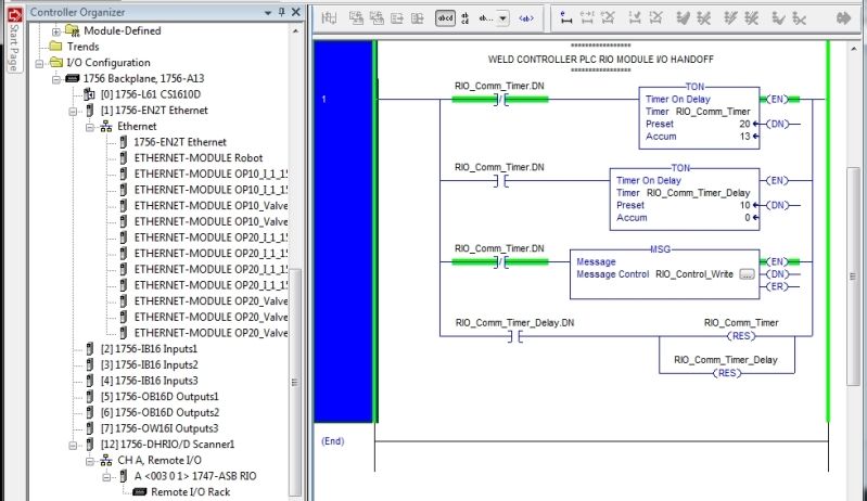
First I have a Compact Logix 5561, which has a 1756-DHRIO module attached, and that RIO module is wired to a MEDAR (RIO Module) that is connected to a SLC-5/03 PLC.

I have attached some pictures of the modules with this post.

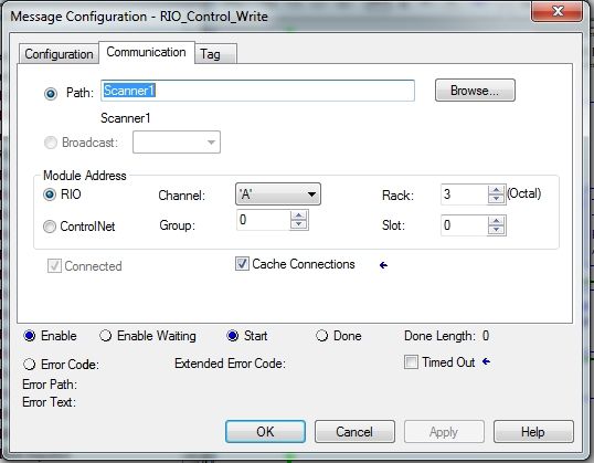
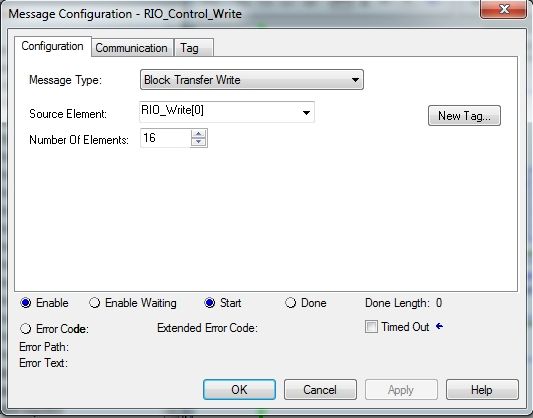
The 1756-DHRIO appears to be communicating just fine with the MEDAR RIO Module based on the communcition LEDs. However, when I try to setup a Message block (using Block Transfer Write) in RS5000, it is not sending the correct bits. It is instead sending the Element number (in binary) only for some odd reason. I have attached pictures to hopefully help you help me. Let me know if you need more information.

Here are some images of my RS5000 and RS500 configuration for the RIO modules:
screenshot1.jpg

screenshot2.jpg

screenshot3.jpg

screenshot4.jpg


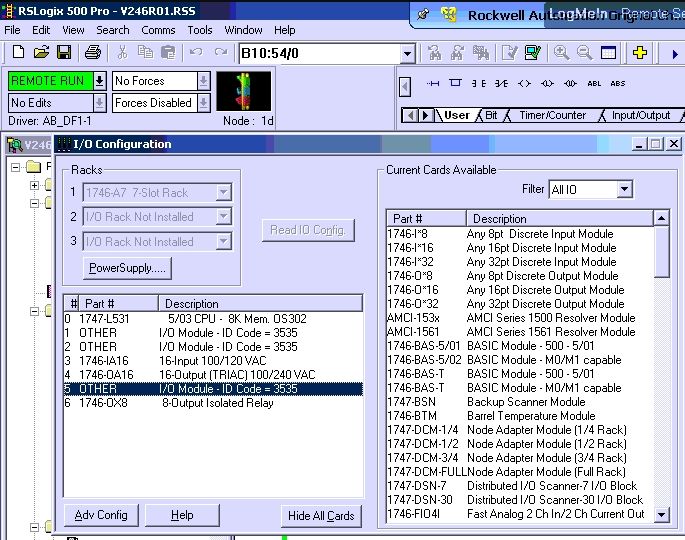
Note, in RS500, it does not allow me to modify the G file or M data since for some reason the MEDAR (RIO Module) comes up as Other, so I'm not sure if this is an issue or not.

photo 1.jpg photo 2.jpg photo 3.jpg photo 4.jpg photo 5.jpg
 
Interesting.

What data type is the array tag "RIO_Write" ?

When you say it's sending the "element number", what exactly do you mean ? Where are you seeing this in the SLC-500 controller ?

Does the Block Transfer complete with a /DN bit, or with a /ER bit ? I frequently use Counters to find out, rather than trying to watch it and catch the bit being displayed.

I'm not familiar with these MEDAR weld controllers. What exact model do you have ?

1. Data type of the array tag RIO_Write is "INT"
2. By element number, I mean the number that you can input into the "Number of Elements" field in the Message block configuration. It shows that bit plus another bit that seems to stay on no matter what. I currently have the Number of Elements set to "7". Refer to the images attached.


3.It completes with an ER bit it seems. I have not seen the DN bit come on yet, and I even made a XIO for it which stayed on forever, unless it's changing states so fast I can't see the green part go on/off.
4. What I found was that the Medar (RIO Module) is really just a basic RIO Scanner but with a MEDAR plate on it, but I cannot remember now. The model number is: 917-0043
attachment.php


Screen Shot 2012-10-22 at 6.49.44 PM.jpg Screen Shot 2012-10-22 at 6.53.34 PM.png Screen Shot 2012-10-22 at 6.54.52 PM.png
 
Last edited:
Write a little logic trap that uses the /ER bit to copy the Error Code from that MSG instruction into a holding register.

Seeing the Length of the Block Transfer in Word 0 doesn't suprise me; that's the I/O image table being used for a block transfer.
 
Write a little logic trap that uses the /ER bit to copy the Error Code from that MSG instruction into a holding register.

Seeing the Length of the Block Transfer in Word 0 doesn't suprise me; that's the I/O image table being used for a block transfer.

It gives the following error:

Map Instance Undefined; or Block Transfer timeout
Error Code: 16#00d0
 
Well, that's unambiguous.

The MEDAR module looks like it's a 1747-DCM module, which could go into a rack with an SLC controller.

Can you point to a user manual that describes if and how it accepts Block Transfers ?

Also, consider the trigger logic you're using for the MSG instruction. From what I can see, it's re-triggering the message every 20 milliseconds. Obviously it can't complete that fast.

For testing, use a simple tag you can toggle just once as the pre-condition for the MSG instruction.
 
Correct me if I am wrong Ken, but he is disabling the MSG Instruction 10 ms after enabling it as well.

Perhaps he could tell us which Make and Model of Welder this is.

A Google search on MEDAR points to http://www.weldtechcorp.com/, but there isn't much information there.

Stu....
 
Well even when I increase the timer, the Error comes on and gives that same error message. I'll have to see if I can find the document that I used to change the DIP switches and showed me that the module was similar to another popular RIO module for the SLC.
 
Your code, as posted, is full of bugs....

Rung 1, top branch, is OK : a self-resetting timer to re-trigger the message, although, as Ken said, 20mS is too fast.

Next branch, starts a "delay" timer from the first timer.dn - seems ok until you realise that on the next scan the first timer gets reset, its .DN bit will go off, so this delay timer will also get disabled, and hence reset - i.e. it does nothing...

Next branch, triggers the message instruction from the first timer. Although triggering it from XIO timer.DN would probably work, it makes more sense to trigger it from XIC timer.DN. That is the way I have always triggered messages, with no problems.

Next branch, the delay timer never gets .DN (see above) unless your scan time is sub 10mS, and anyway resetting the message trigger timer could cause the message to re-trigger before it had completed or errored.

I have always triggered RIO messages as in Pic1. For systems with a lot of messaging, I have seen a "backing-off" strategy as in Pic2, (not my idea) and it assumes the message error was caused by RIO timeouts, so it slows down the re-trigger until it starts to work again. As I said not my idea, but could work ok if you are not interested in getting the I/O data passed on a consistent timebase.

Pic1.jpg Pic2.jpg
 
Your code, as posted, is full of bugs....

Rung 1, top branch, is OK : a self-resetting timer to re-trigger the message, although, as Ken said, 20mS is too fast.

Next branch, starts a "delay" timer from the first timer.dn - seems ok until you realise that on the next scan the first timer gets reset, its .DN bit will go off, so this delay timer will also get disabled, and hence reset - i.e. it does nothing...

Next branch, triggers the message instruction from the first timer. Although triggering it from XIO timer.DN would probably work, it makes more sense to trigger it from XIC timer.DN. That is the way I have always triggered messages, with no problems.

Next branch, the delay timer never gets .DN (see above) unless your scan time is sub 10mS, and anyway resetting the message trigger timer could cause the message to re-trigger before it had completed or errored.

I have always triggered RIO messages as in Pic1. For systems with a lot of messaging, I have seen a "backing-off" strategy as in Pic2, (not my idea) and it assumes the message error was caused by RIO timeouts, so it slows down the re-trigger until it starts to work again. As I said not my idea, but could work ok if you are not interested in getting the I/O data passed on a consistent timebase.

Yeah I figured my timing part needed some work, but still would that cause it to send the Number of Elements to the RIO Module connected to the SLC? I've tried not having a timer at all and just having a XIC that I turn on myself and leave it on until it Errors out, and the same issue occurs. The thing is, it is transferring something, but just not the right data.
 
Don't sweat the timing logic... we'll sort that out later. Everybody has their favorite method (including those who do it all wrong !).

Block Transfers work by multiplexing data through the first Word of an I/O connection. Think of it like passing numbered words through a mail slot until they can be reassembled on the other side into a paragraph.

The reason you're seeing the Length in the first word of the Input data in the SLC is that it's part of the header for a Block Transfer.

What you're showing ought to work, but I don't know these weld controller modules at all. The old 1747-DCM, as far as I've ever seen, doesn't support being a block transfer target.
 
But those old 1747-DCM user manual doesn't say anything about accepting block transfers. That's my recollection, too.

That's why I wonder if the weld-controller version is different, and does support block transfers.

There's got to be some sort of manual that told you that you needed to perform block transfers to the module, right ?
 
There's got to be some sort of manual that told you that you needed to perform block transfers to the module, right ?

:whistle:Not exactly. To cut a long story short, it was assumed from those having me work on this project that communication between the Compact Logix and the SLC would be possible using the MEDAR (RIO Module).

So after googling around and trying this and that, I saw someone using a Block Transfer (something I had not tried yet), and started to give that a shot. As you can see, there are not many manuals for this particular MEDAR (RIO Module) for some reason, but since we were able to finally get the COMM light to stay green and get a CH A ok light, we figured communication may be possible.

What other methods could I try other than a Block Transfer?
 
I believe the manual I followed was the one attached, and when I followed it correctly and changed the DIP switches based on my configurations, the COMM LED light finally went green and stayed green.

It setting up the Module following the 1747-DCM Instruction Manual worked, we will have to assume for the time being that it is a 1747-DCM or a Clone. Looking at the pictures, and the Manual information, it physically resembled a DCM Module. The 1747-ASB has 3 DIP Switches.

So after googling around and trying this and that, I saw someone using a Block Transfer (something I had not tried yet), and started to give that a shot. As you can see, there are not many manuals for this particular MEDAR (RIO Module) for some reason, but since we were able to finally get the COMM light to stay green and get a CH A ok light, we figured communication may be possible.

What other methods could I try other than a Block Transfer?

Following the assumption above, the DCM Module Data is not Read/Written with Block Transfers, but with PLC Addresses. The Scanning PLC Address is based on how you set up the Dip Switches for the Rack and size. The SLC PLC Addresses are based on the Slot it is installed in. This is discussed in Chapter 3 of the Manual you posted the Link for. Your job will be complicated by the fact that the ControlLogix handles Addressing differently.

Do you have any other existing installations to compare to?

What Hardware and Firmware Version is your DHRIO Card?

Stu....
 

Similar Topics

so after a previous thread about the panelview 1200. I figured everything out that I needed to get working with it. I've got the RIO discrete...
Replies
5
Views
1,575
Hello all, I couldn't find a solution through the search tool so hopefully someone out there can help me along. I'm working with a converted...
Replies
3
Views
1,195
Hi All, First time caller, long time listener... Have a new system in the field with a new controllogix 1756-DHRIO talking to 6 existing chassis...
Replies
9
Views
5,749
Greetings, I replaced a 1305 drive with a PF70 drive. The 1305 was controlled by a PLC5 via RIO using a 1203-GD1 Remote I/O Communications...
Replies
7
Views
8,918
Hello, I am currently using a Control Logix with RSLogix 5000 trying to communicate with my 1794-ASB(Has a power supply, adapter, 16 point input...
Replies
10
Views
6,034
Back
Top Bottom