How do i do this???

Daniel81

Member
Join Date
Oct 2012
Location
Mansfield, QLD
Posts
17
Hello I am new to PLC programming.

The problem I have is this,

I am writing a program for a garage door. When the door has completed three operations (Up/Down = one operation) it is supposed to be locked out.

The door has an upper and lower normally closed magnetic switches.

The door must start in the down position.

The issue is when the door is down before it has done any operations the up counter counts this as one.

I am trying to use a latch and unlatch but I cannot get around this problem.

Any assistance would be most appreciated.
 
From your description it sounds like you need to use the off transition of DOWN to trigger your counter. Some processors support differentiated contacts to do this but if yours doesn't there's another way.
Create a coil that is ON when your DOWN input is on. Place it in the next rung immediately after your counter in the program. Program your counter to count when the DOWN input is OFF and the coil is ON. That condition will only be true for one scan as the DOWN input goes off.
 
Welcome to the site Daniel
Zip up your current program and post it
I am unable to look at it at the moment but many others can.
 
This is a quick and dirty brute force solution to give you an idea.
Hopefully, I understood your Input Device States properly,

Stu....
 
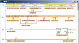
Good job, Stu. Another method that might work (depending on details of the assignment) is simply to use the Lower or Down motor output to trigger the counter, (no latch or unlatch needed) like this picture, shown after 3 cycles. The door cannot be raised unless the counter is reset to 0.

Door Opener with Cycle Lockout.jpg
 
Last edited:
Lancie1 I am new to plcs,i have looked at your program and shouldn't the stop button be n/c so when you press it it breaks the circuit ?it looks like you have to press the stop button and the open to get it to open thanks stu
 
Stop buttons are normally hard wired as a normally closed contact.
so the Input is ON - energised
as a result the program contact needs to be OPEN
- this may be the oposite case when using a simulator - A N/C input may not be possible

THIS IS NOT RELATING TO SAFETY DEVICES
 
...should the rung 0 open limit switch be NC? or seems like door won't open.
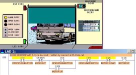
No, it won't work that way. The simulator has these switches pre-defined, and this one happens to be the opposite of what your intuition would say. The LogixPro Simulator was designed to train students not to make any assumptions about what things "should" be - just like the real world. Here is a picture that shows the actual setup. The UP Limit switch is unactivated but closed with the door not open, but the DOWN Limit switch is unactivated but open with the door not closed. Don't AssUMe anything - you will learn what AssUMe makes of you and me.

Door Opener Simulation.jpg
 
Last edited:
Yep your right Lancie1 - gotta keep reminding myself of the simulator setup
 
Back
Top Bottom