PLC diagram from

Join Date
Nov 2012
Location
delhi
Posts
12
I'm given a ladder diagram as follows:
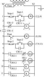
Problem.jpg.

I need to have a PLC 5/30 control System. There are 8-point I/O cards with one-slot addressing. the input cards use slot 0 and the output cards use slot 1. I have constructed a PLC ladder diagram as follows:
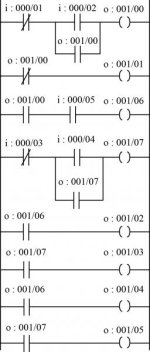
Solution.jpg

The CR's in the problem are used as both input and output in the solution. Is it correct to address the outputs as inputs in PLC (as in the last four rungs)?

Greatly appreciate your help..
 
Just quickly, before anybody else says something....
Have a think about your stop button

And where did the O/L's go?
 
I thought I could avoid using the OL's. I'll add them, if they are mandatory (i know they are used to secure the motors, but not sure if we need them in the PLC diagram).
 
To include the overloads in your ladder for the plc you will have to use the the auxillary contacts from your motor overload device or MP and connect the NC contact as an additional input to your PLC , for example overload connected to I:000/06 and adress it as such in your ladder to disable the motor output when false (or NO contacts when true)
 
you need to look at the program also as it is not correct.
-
Ask what the system does.
and write it down in step form as you have missed an important step.
-
Start with 'Power Off' step.
-
as far as the O/L's how do you protect your motor with out these.
-
Hint to steps - the first pointers
1. power turned ON = Green Light ON
2. Start Button Pressed = Green Light Off
3. Enable main control power = look at rung 4
 
Relay Logic Conversion to Plc-5/30 Learning Program

Mayank,

Now that you have had time to study and think, here is my version of your PLC-5/30 program, using the first available bit in Slot 0 for the Inputs and Slot 1 for the Outputs. Of couse this program could use 3 fewer outputs because CR1, CR2, and CR3 could all be B3 internal bit relays.

I did set up the two STOP buttons correctly, using XIC instructions to look for NORMALLLY CLOSED stop PB's. I also put the CR1 relay contact in front of all rungs from the Green Light (Rung 002) to the end, just like your relay ladder logic.
 
Last edited:
my output will be ON for maximum 15 clock cycle but at the same time after clock cycle 4,5& 6 output will off & will not hold for 15 counts as set
 

Similar Topics

Q(1) Design a controlling system using DVP-40ES Delta PLC for a threestory Elevator Prototype as shown in the figure below. Show in details the...
Replies
4
Views
2,147
Is there an ISA or IEEE standard which details symbols that one would use to create a logic diagram representing the PLC program? I only have a...
Replies
2
Views
1,485
I want to connect PLC MODEL NO:CP1l with console model no:PR001.please help me out how to connect and also state plc cable connection.i will be...
Replies
1
Views
1,650
Dear All, Pls help me to make a programming cable from Rs232 to Rj45 for Fuji(SPE) NW0 plc.Please please please. [email protected]...
Replies
0
Views
1,431
HEY there, could someone please answer this Design a plc ladder diagram to control a production line of filling bottles with two conveyors upper...
Replies
6
Views
2,267
Back
Top Bottom