ML1100 Perform Operation Every Scan

agentnumber2

Member
Join Date
Jun 2012
Location
Alberta
Posts
8
Hi Gentlemen,

I was hoping to perform a mathematical operation every scan on the ML1100, and I cannot seem to get it to work. Just to test it, I have a single rung that is taking the input from AI Channel 0 and multiplying it by itself, the the rung below it adding up the squared values (attempting to get an RMS value... eventually).

Do I need to put a special NC contact before the operation, or should I just leave it as a rung with the mathematical operation?

Thanks!
 
The math instruction should update each scan but its possible the analog input is not.

An unconditional rung should work.

Is the AI coming from an analog input card ( catalog number please) or the embedded input.

Can you post your program? Zip it first.
 
For now, it's coming from AIN directly on the 1763-L16BBB, but I will be getting a spectrum controls 1762sc-if8u tomorrow or the day after.
 
Do I need to put a special NC contact before the operation, or should I just leave it as a rung with the mathematical operation?

With Allen Bradley PLCs there is no need for a Contact on the Rung in front of the other Rung Elements. As Mickey said, the Math Instructions will Execute every Scan. However, once you have your final PLC Code for your Calculations, you probably won't want it to Execute every Scan. That is where the One Shot Instruction is useful.

You can find the ML1100 Instruction Reference here;

http://literature.rockwellautomatio...blic/documents/webassets/browse_category.hcst

I am have issues with the ML1100 Page, so hopefully it will work better for you.


Stu....
 
For now, it's coming from AIN directly on the 1763-L16BBB, but I will be getting a spectrum controls 1762sc-if8u tomorrow or the day after.

I looked at your Offline copy of the PLC Program, and it seems alright. Can you Post a Live Online Screen Shot of it operating?

Stu....
 
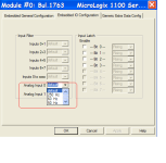
Check the analog filter setting to improve responce time. See Text from help online help and picture below.

Input Filter
The input filter response times can only be adjusted at the time your program is developed.

The specific parameters displayed will vary depending on the specific hardware defined.

Select an input filter for each group of inputs. In some groups not all input filter settings are available.

The input filter response time is the time from when the external input voltage reaches an on or off state to when the micro controller recognizes that change of state. The higher you set the response time, the longer it takes for the input state change to reach the micro controller. However, setting higher response times also provides better filtering of high frequency noise.

Analog_Filter.PNG
 
have you given any thought to how big these numbers are going to get - and to how well they're going to fit into the integer locations that you're trying to use? ...

suggestion: using a calculator and a pencil and paper, go through a couple of reasonable examples of how you think the math should work out ... then see if those numbers could possibly work given the limitations of the integers in the PLC ...

TIP: pick some examples at the low end, the high end, and something near the mid range of the values that you expect to see from your input ...

I'm not 100% sure about what you're trying to accomplish, but I've got a hunch that another format (floating point or long-type locations) might be better suited to your project ...

going further ...

depending on the resolution (and the update speed) that you're shooting for, there's a chance that the processor just isn't going to be capable of doing the math that you're expecting it to do ...
 
Last edited:
Another reason you may not see the results every scan is that your PC/Laptop itself is not fast enough the display it every PLC scan.
 

Similar Topics

I'm looking to implement a low-cost, efficient method of communicating some integer values to an R30iB robot from a Rockwell 1100 PLC. I am not...
Replies
8
Views
1,723
Hello all, I am trying to setup my MicroLogix 1100 as a modbus RTU master for a modbus network containing multiple modbus RTU slaves. I currently...
Replies
7
Views
3,916
We have a machine that keeps losing its program at random intervals; sometimes 2x-3x in a shift, sometimes will go over 1wk without issue. I had a...
Replies
9
Views
2,929
Just asking for clarification here, but from my research all I need is a 500 ohm resistor across the AI and the common? Heres my schematic. I...
Replies
5
Views
2,577
I have a CLX L61 and I'm trying to read from and write to a Micrologix 1100. I'm attempting to read 200 REAL elements but I'm receiving an error...
Replies
2
Views
1,458
Back
Top Bottom