A noob aproach to Mitsubishi PLCs

drinker

Member
Join Date
Nov 2012
Location
Osaka
Posts
9
Hi guys!

Recently in work I found myself in a position where I had to, almost, mindlessly change a heating current on some evaporating cell not to overstep a given heating speed value. This bothersome task had to be repeated for every cell and a reversed procedure had to be applied for cooling, absorbing a fair amount of time that could have otherwise been utilized in a far more productive way. This led me to the idea of developing a PLC program that could handle this task automatically. Unfortunately I had no idea how to implement it since I had no experience with PLCs before.

After reading a significant amount of materials on the topic I could say I know the basics of programing the PLC, however I cannot yet find answers to some critical implementation aspects of this, perhaps soon to be, program.

So to be more specific, I'm using a Mitsubishi A series (A2A) cpu with a few I/O modules (and of course a power unit). The heater current controler is a KIKUSUI PAK35-20A (and a KIKUSUI PAK60-18A) and for temperature monitoring a RKC REX-G9 is being used (and a YOKOGAWA UT551E - which replaced one of the rkcs that broke some time back). The PLC is connected to a PC via a Interface PCI-2424 card.

Ok, so the first, and by far the most important, question addressed to all you pros gathered around this forum is whether it is possible to control the temp. of a cell using the aforementioned current controller whilst monitoring the heating rate via the REX-G9? From what I have checked the cabling around the machine - it seemed that the REX-G9 is connected to be PLC via it's analog output 31 and 32. The KUKUSUIs connect to the PLC by the GPIB output (not sure about this one - will have to check again).

Another question to answer would be as to how can a user, at the PC terminal, set the target temperature for the program (as to whether to cool down or heat a particular cell) running on the PLC. Although my first idea would be to just send some data to the PLC and just have the program check the serial comm memory for changes. But I'd like to hear your views on that.

That's it for now. I'd have some more questions but they can wait a bit :nodi:.

Thanks in advance,
Mike
 
question 1 yes good possible with PLC.
you will have to give all in/outs of the system.

if you give the strategy ( i know what cells are) it may be possible to have it more efficient running, and fully automatic with a PC as HMI
 
Just to upset the apple cart
the A series is no longer supported by Mits..
you will need to look at the Q series
your future issues will be many if you dont
 
Not so easy

question 1 yes good possible with PLC.
you will have to give all in/outs of the system.

if you give the strategy ( i know what cells are) it may be possible to have it more efficient running, and fully automatic with a PC as HMI

Thank You for your reply - unfortunately I was unsuccessfuly looking for some documentation regarding the I/Os in my system. As you can see in the picture below, figureing out the wiring physicaly is rather impossible due to bundling of all the cables together.


However you can also see eleven digital inputs (which is exactly the number of RKC temp. moniters) and also some analog I/Os - I don't think there is much aparatus involved apart from the heaters - so I guess the only difficulty is to figure of which one is which.

And here comes one problem I've been having: I can't connect to the PLC using GX Developer (the most recent version, I think, but demo). I get an error saying:

Code:
Cannot comunicate with PLC for one of the following reasons.
Communications timeout
Cable error
Specified transmission speed not supported for connected PLC
Monitor condition set status is read by device
The project PLC and the connected PLC are different.
 
<ES:018084b>

Well, as I said earlier, I'm using a Interface PCI-2424 card to connect to one of the PLCs input modules and I'm not sure It can be considered a serial connection - which is the setting in Developer. Do you have a sugestion regarding that?

Best regards,
Mike
 
Last edited:
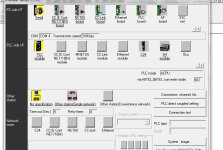
The GX version is 8.102G and the cable came with the board so i guess it's a CAB-53xx series cable (which works fine because I tested a sample program that lets you open shutters and it works) - it connects directly to one of the input modules. So I would be guessing the problem is configureing GX to work with it.
 
Are you using USB converter
Please check your CPU and Seriel setup
Even stare a new file - you mest set up as an A series

acpu.JPG
 
Ok, I had to postpone the development for some time since I couldn't connect to the PLC. Unfortunately I still can't do that because I decided I'd make the cable myself (probably bad idea - but I couldn't find a proper programing cable around my area so there it is) using a CP2102 based USB UART to TTL and additional MAX3467 IC. I assumed the PLC uses simple RS-422 for the connection, without any CTS and RTS stuff - just pure TxD and RxD. I guess the assumption was wrong since I still can't get a working connection to the CPU. Can anyone comment on what features of RS-422 the mitsu A2A uses?

Thanks again,
Mike
 
Ok, I have a cable now that certainly is working, in a sense at least. Because every time I plug it in the PLC restarts, which scared the hell out of me the first time it did that - and ever since then I haven't tried again. So the big question for now is if that is how it's supposed to be. I can imagine a scenario where hot-plugging the PLC makes it restart - and that would be considered normal. However it may also mean something's terribly wrong with the wiring. I can't seem to find any info on this in the manual so I wondered if someone could help me out here.

Thanks,
Mike

Btw. I was checking operation of the cable with Realterm and it picked up a transmission from the PLC before (or maybe after - not sure) the restart.
 
either of the standard cables, USB or STD, for the mits. allows hot plug in with no stopping of the PLC
there is something wrong
 
either of the standard cables, USB or STD, for the mits. allows hot plug in with no stopping of the PLC
there is something wrong

Yeah, I found the error causing an overvoltage. I switched VCC with GND in one of the pins, lol.

Anyway, after clearing that up I tried again but to no avail. I used the schematic below to assemble it (with some modification - using MAX3467 and a UART to USB module)
mitsubishiplccableschem.gif


but something is still not working. I wasn't sure if the outputs for RTS+/- should be reversed, i.e. RTS+ should go to VCC and RTS- to GND. I tried both these and it didn't work anyway so I'm at my wits' end. In a different schematic also pin 25 was connected to VCC so maybe I should try that.
 
Ok, I'm officially desperate. Here is the schematic of the cable I made

cablek.png


Could somebody please tell me the mistake I made and why it's not working?

Best regards,
Mike
 
Ok, so you just about f_€ked your PLC from using the wrong cable and you may have ruined the comm port. People with AB's on DH know the damaged that can be done. Man, you got balls. Is it possible to obtain the correct cable from mitsubishi or a reputable after market equiv??? At least then you know the cable is not the problem.
With regards to having nothing available locally you can certainly have this in two weeks which is shorter than the time and effort put into your back yard cable that may have ruined your CPU.

http://store.plccables.com/Mitsubishi--USB-SC09_p_17.html
 
Last edited:
Well, I'm currently waiting for a cable I bought at ebay. I'll just have to wait. But this should work fine to, I think...
 
Yay! A minor success in the struggle of man against machine ;). I've got my cheap-*** cable from china today that fortunately works like a charm. So I was able to download the program running on the PLC - 1560 steps...

Well, now I only need to identify the inputs and I'll be ready to go. So the question now is how to do that? From what I observed the KIKUSUI current controllers do shut down as the PLC resets itself. This behavior should leave a characteristic mark, in my opinion, in the ladder diagram. However I'm not sure what to look for - any suggestions?

Thanks in advance,
Mike.

PS. My cable didn't brake anything! Yay - however it still puzzles me why it didn't work. I shall probably do some more testing later.
 

Similar Topics

I work in a field where our plc and hmi are constantly being powered fully off and on daily before being sent out. I am new to the world of plc...
Replies
5
Views
958
Please laugh… but can I take 24volts from an IO module and wire it straight into its own input card to simulate an input….?
Replies
5
Views
1,259
I need to be able to open a customer's FT View project and make any changes if necessary. Which one do I need??? :hmmm: I don't want to have...
Replies
10
Views
2,591
Hello all, i will start off by saying i know nothing about load cells, i want a converter/amplifier to output a 4/20mA signal from a load cell...
Replies
14
Views
5,390
Hi All, I don't have a ton of experience with PLCs yet, so I appreciate any feedback I can get. What I am doing is using an Omega FMA1816A mass...
Replies
7
Views
1,821
Back
Top Bottom