sfindley
Member
It's been awhile since I've posted but I finally found a project at my new job where I get to play with a PLC!
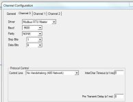
We have a control system for our ventilation system that used a PC and modem to communicate with a ring of Square D Powerlink G3 controllers. The modem connected via a Niobrara QUCM module and used Modbus as the communication protocol. There are 16 controllers on the network. Apparently, the communication system hasn't worked in a long time and the upgrade for the system is VERY expensive. I was thinking that I could use a MicroLogix 1400 in lieu of the modem and QUCM module and add the benefits of a PLC to add more control, HMI and temp/humidity inputs to the system.
The problem I have is that I've never messed with Modbus before and I'm trying to make sure I understand if/how it is going to work.
If I understand Modbus correctly, I can set the PLC up as the master and use it to poll each of the slaves using messages. Different message commands elicit different responses from the slaves (i.e. report coil status, write coil, etc) Each controller will only respond to a message that is addressed to its node. Because it is serial communication, with 16 nodes, the total read time on the circuit can be quite large.
I have some questions/thoughts about this project.
1. Will I need a protocol converter?
I have the Modbus register map for the G3 controller, so I should be able to read the message into registers in the PLC and then parse them out based on the map, right? The ML1400 specifically states that it natively uses Modbus RTU/ASCII so it seems that no converter would be needed.
2. Can I set the PLC messaging up to only poll sections of the controllers at a time in zones?
For example, break the 16 controllers up into four zones. When that zone is selected on the HMI, enable the messages associated with those controllers and not with the other 12. The HMI will only be displaying the “active” zone, so it will only need the info from those controllers. Does it work that way, or do they all have to communicate in order? It seems that if I can do it that way I can reduce the overall read time. This system is not highly dynamic so there isn’t a need for “real time” update, just somewhat quick updates.
Any help/guidance you guys can give will be greatly appreciated.


