OT: Motor Wiring Question

Join Date
Apr 2002
Location
Just a bit northeast of nowhere
Posts
1,117
We've got a pump motor that was delivered that is 220 VAC single phase. What went unnoticed is that the manufacturer has a different definition of single-phase from what we're used to.

The pump is wired L1-N-PE, with L1=220 VAC to Ground

We are used to L1-L2-PE, with L1 and L2 = 120VAC to Ground

What I'm trying to sort out is, if it's safe to connect N to L2 and run the pump with existing power.

Any thoughts?

Thanks,

TM
 
Your new pump voltage is 220 VAC from line to line (whatever you call the terminals).

Your L1-to-N is probably 120 VAC. This motor would not work very well on 120 volts. Many small U.S. single-phase motors have wiring-terminal provisions for dual voltages, so they can be converted between 120 and 240 volts. I would bet that your motor was not made in the U.S.

If you have a spare 2-pole circuit breaker in the same panel, run one more wire out to the pump and run it on 240 volts, L1 to L1 and L2 to "N" (if that is what the second terminal is labeled).
 
Last edited:
Like I said, what you call the motor terminals varies from country to country, whether there is a terminal called "N" is not really important for the motor operation. Their "N" is not necesarily the same thing as your "N". For a single-phase motor, all that is important is the measured voltage and current level from Line 1 to Line 2. If you apply 230 volts (at the proper current rating) across any two motor terminals that are rated for 230 volts, then it will run.

PS: Having motor terminals labeled "L1" and "N" implies that this is a dual-voltage motor, and there is a another third line terminal somewhere (perhaps an "L2" to run the motor at 460 volts?), or that the motor was built in China.
 
Last edited:
I think you have a labeling problem.

However gotta do some definitions first.
First the Neutral. The Neutral is a current carrying conductor referanced to ground potential at the service entrance by bonding to the ground electrode system. Commonly labled N and colored white.

Here in USA 120 is derived from two sources
1. Edison 3 wire by means of a center tapped transformer secondary. L 1 and L 2 are non grounded current carrying and have a potential of 120 to center tap the nuetral or ground. Potential between L1 and L2 is 240.

2. 120 208 wye here L1 L 2 and L3 are non grounded and have potential between them of 208. The neutral is derived at the star point of phase windings and bonded to ground at that point. Potential between L1 2 or 3 to neutral is 120.

Now to your motor. Factory should have identified the line leads in yur case as L1 and L2 to get techincal about it. Well they did not.

ASSUMING nameplate says 240 or maybe 230/208

Check from N to ground AND from N to L1. If no continuity to ground ie motor frame and continuity to L1 it should be OK to hook L2 to the terminal labeled N and it will run OK.

IF motor is really wound for 240 and you have only 208 it may be OK. You are pushing the boundary of undervoltage so keep an eye on it for overheating.

Dan Bentler
 
It is a common "labeling" thing. Or "mis-labeling" if you prefer. You have to be a little more careful with electronics (especially from Europre) because of the methods they sometimes use to employ their EMC filters. With a motor as Dan mentions there should be no real distinction between L1 and L2. It was probably made in a country that forgets that not everyone else grounds one leg of their single phase 230vac. The flip side is, if there was some internal chassis connection of that phase to ground there would be no way to ensure that your saftey ground was not sharing the current with the "neutral". That would obviously be a big no-no.

I see the same thing over here a lot as well. Many product manufacturers assume that if it is 115vac that one leg must be (neutral). Granted, it is much more common that way because you don't have to put in circuit protection for both legs, but it is not mandatory.

As long as you have a good saftey ground to your motor chassis and you ohm an open circuit to ground from your winding you should be fine.
 
We've got a pump motor that was delivered that is 220 VAC single phase.

Thanks for the answer, but that's not what I mean:

The pump is built for 230 VAC from L1 to N.

And my guess it's also meant to run on 50Hz

I have available 230 VAC from L1 to L2.

My guess is that your system is 60Hz

Not sure if I can connect the pump to my single split-phase source.

Thanks again.

TM

If this is a centrifugal type of pump my guess is you will be starving the motor for voltage at 60 Hz
 
Tim

I can see this is going to become conjecture cubed. Please send photo of nameplate.

Also a better description of your power supply to motor. The term split phasee refers to a particular motor design. Voltage readings L1 to L2 and L1 and L2 to neutral will suffice very nicely.

Sorry did not pick up on it being a pump motor.
IF
driving centrifugal pump and you are running pump to full capacity
THEN
be very careful running it if 50 Hz motor and on a 60 Hz line. Instead of derating and running less load under conditions above you are running at more load (power proportional to speed cubed). Try it but watch line amps very closely and make sure does not overheat.

Dan Bentler
 
connect L1 to L1
and the N to L2
make sure the capacitor value is correct for 60 Hz.

it will run 20% faster and take up 50% more watts, so it will heat up more.
 
if it is a 240V motor the N connection is purely a terminal from the motor.
Our 'N' is normally grounded to earth in Australia - but this is not done internally on a motor or device like a drive.
so L1=L1 and L2=N and PE = gnd should be fine
as mentioned be wary of the capacitance
 
It will run 20% faster and take up 50% more watts, so it will heat up more.
Why would it heat up and so on (because the motor (as far as we know) is rated for the applied voltage and frequency)?
 
Last edited:
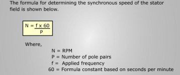
supose when you do the calculations for the Synchronus Speed
as below
But I would expect no issues for cooling/heating unless the motor is running under its designed speed (via a VFD)

mtr spd.JPG
 
Is this an imported pump? About 10 years ago I purchased a that was imported and required 220vac. We installed a transformer that went from 480v to 220v with a single leg to ground measuring 220v. It's been too many years to remember the specifics, but I remember that it was not the same as a standard 480 to 220 transformer.
 

Similar Topics

Found that a trouble some pumps that kept causing overcurrent faults on the VFDs were wired in star instead of delta configuration. In star...
Replies
6
Views
2,620
Hello! We have an older Hobart mixer/chopper which has a shroud around the motor with the nameplate data affixed to it. On the nameplate, it...
Replies
5
Views
3,572
Greetings everyone...We have an old 230V 3 phase 2HP motor we received in on a used tank. We're curious how it is supposed to be wired. I did a...
Replies
9
Views
3,445
https://imgur.com/a/kKPtzyP We are making improvements to these motor controls by replacing these old resistor banks and DC generator with DC...
Replies
3
Views
1,783
Does anyone have a wiring diagram for an ABB motor. MBT 180L. The motor doesn't have a diagram anywhere on it, or in the junction box. Ive tried...
Replies
2
Views
2,308
Back
Top Bottom