2-wire analog transmitter

david90

Member
Join Date
Apr 2010
Location
ca
Posts
202
I'm reading the datasheet for the ab 1746-NI4V and I'm wondering if 2-wire transmitters are always current analog signal generators. Since a 2 wire transmitter doesn't require power (no + and - terminal for powering the device), is it always a passive device like a thermistor?

2a0f6fs.jpg
 
A 2 wire transmitter DOES need power, but current/voltage drop just to power the sensing circuitry is very small.

The output current is adjusted to allow for this small amount so that 4 ma reflects the low reading properly. (Another reason why 4 ma instead of 0 ma is used for the low point. Another being line break or transmitter failure detection.)
 
Last edited:
I'm wondering if 2-wire transmitters are always current analog signal generators.
Answer: Yes, a 2 wire transmitter is always a current signal, because as Bernie points out, about 3.6mA of the signal is used to power the instrument to get the readings. That doesn't happen with voltage output devices, which need to be 3 or 4 wire.

Since a 2 wire transmitter doesn't require power (no + and - terminal for powering the device).
It does require power. Your wiring diagram shows an external power supply, typically 24Vdc.

It's called a two wire transmitter because power is not wired to it separately, the power comes from the 3.5mA below the zero signal level. Fewer wires are a really big deal in a refinery that has 10,000 instruments with lengthy home-run wiring.

is it always a passive device like a thermistor?
A 2 wire device is called a 'passive' analog output because the power comes from somewhere outside the device, but that's not passive in the sense of the changing resistance of thermistor. Active analog outputs are powered by the power connected as a 3 or 4 wire device.
 
If it helps, think of it this way....

A "passive" 2-wire device cannot drive current through the circuit - all it does is regulate the current to 4 to 20mA. To do that, it must not consume more than 4mA to power its own electronics, otherwise it could never signal minimum scale.

An "active" 3 or 4 wire device takes its power supply from a separate source, and uses this to drive a 4 to 20mA signal to the receiver.

hth
 
I'm reading a text on analog input module, and according to the author, the maximum measurement error of an analog input module is "Verr = (Vmax-Vmin)/2R." (Vmax-Vmin) is basically the operating voltage range of the module and R is the number of counts.

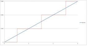
I think the equation "Verr = (Vmax-Vmin)/2R." is wrong. As an example, consider a 2-bit module that has a 0 to 10 operating voltage range. The calculated voltage increment per count is 10/[(2^2)-1] or about 3.333V per count. The graph shows the relationship between the input voltage and the counts.

I applied the equation "Verr = (Vmax-Vmin)/2R" to the example module, and i got a max error of (10-0)/(2*4) or 1.25. However, from the graph I can see the measurement error being greater than 1.25. For example, if I input 3.00V, the count would be 0 and the error would be 3.00V.

So is the author wrong or am i wrong? I think it makes more sense that the max error is defined by the equation Vmax-Vmin / 2^n-1.

34i09qf.png
 
Last edited:
The 4 code digitizer as you describe would switch at 1.666, 5.00, 8.333 volts. So at any point the error would be 1.666 volts maximum. It's a stair step which goes above and below your slope. See the red line I placed over your drawing.

34i09qf.jpg
 
Last edited:
The 4 code digitizer as you describe would switch at 1.666, 5.00, 8.333 volts. So at any point the error would be 1.666 volts maximum. It's a stair step which goes above and below your slope. See the red line I placed over your drawing.

how did you come up with the switch points? Are switch points the moment the count increases? I'm confused by your graph.
 
The red line is graphing the increasing counts (0, 1, 2, 3). I guess we need another scale legend on the right hand side. In A/D convertors I have seen the first count ( 0 -> 1 ) is as the resolution/2. The next ones are spaced one resolution apart. The last one occurring 1/2 resolution before the max value. This leads to the inaccuracy being at most 1/2 the resolution.
 
The red line is graphing the increasing counts (0, 1, 2, 3). I guess we need another scale legend on the right hand side. In A/D convertors I have seen the first count ( 0 -> 1 ) is as the resolution/2. The next ones are spaced one resolution apart. The last one occurring 1/2 resolution before the max value. This leads to the inaccuracy being at most 1/2 the resolution.

U threw a monkey wrench into my understand of analog inputs. Anyway, I think the graph makes more sense if the axis are switch where the count is vertical and the input voltage is horizontal. The graph i posted is consistent with your switching points.

I still don't see how the maximum error is 1.666V for ANY point. For example, if I were to input 4V, the count would be 1. A count of 1 equates to 1.666V and therefore the error is 4-1.666 or 2.33V.

However, I can see how the error is 1.666V max in the region between count 0 and 1.

2s6kg09.jpg
 
No, one count still equals 3.333 volts. So at an input of 4 volts with the count at 1 the difference is .666 volts. When the input is approaching 5 volts the error is approaching 1.333 volts low. It then switches at 5 volts. Now the count is 2 representing 6.666 volts. It's 1.333 volts high now but the error is dropping as the input continues to rise. The difference is never more than 1.666 volts. I think you were confused by the first switch at 1.666 volts. The intent is to yield a count. multiplied by the resolution. which is never more than 1/2 the resolution away from the input.
 
No, one count still equals 3.333 volts. So at an input of 4 volts with the count at 1 the difference is .666 volts. When the input is approaching 5 volts the error is approaching 1.333 volts low. It then switches at 5 volts. Now the count is 2 representing 6.666 volts. It's 1.333 volts high now but the error is dropping as the input continues to rise. The difference is never more than 1.666 volts. I think you were confused by the first switch at 1.666 volts. The intent is to yield a count. multiplied by the resolution. which is never more than 1/2 the resolution away from the input.

Thanks for the help. I see what you mean now. I always thought the switching is done at the count.

Would the switching points be the same for an analog output moduule?
 
I don't know. With an output module you know you have specific output values. You know you can't create the in-between values. Though if you module has a small enough resolution it may not really matter.

An input module is trying to generate a numeric approximation of a infinetely variable input. So it is not quite the same thing. But again, with a small enough resolution this whole thing may be rather pointless.

But the input numeric approximation is even more reasonable if you think of a module which accepts a voltage range from minus to plus. You would expect a numeric reading of zero spanning by 1/2 of the resolution on each side of the actual zero voltage input.
 

Similar Topics

Does anyone have experience wiring this type of analog pressure transmitter up? It's 4 wires. 3 blacks and 1 green which I assume is earth...
Replies
9
Views
257
Hi, Calculation of voltage drop of a 2 wire transmitter connected to plc AI is pretty simple and straight forward. My Question is could you...
Replies
4
Views
2,122
Hey folks, Hardware: *=Must use these devices. Allen Bradley 1734-AENTR (Dual Ethernet Adapter)* Allen Bradley 1734-IE8C (8Ch Analog Input...
Replies
2
Views
701
An analog Transmitter (Sensor) with 2 wire and 4 to 20 mA output, is connected to an analog input module. The sensor requires an external 24 vdc...
Replies
5
Views
2,192
Hello everyone, I'm new to the forum and I've never work with analog sensors before. How do I wire up 3-wire ultrasonic analog sensor to Allen...
Replies
3
Views
1,897
Back
Top Bottom