Timer Problem

David Strang

Member
Join Date
Feb 2013
Location
San Jose
Posts
20
Giday
I have a 1760 L12AWA series A Rev A.
In the circuit diagram I have
P2- button- Timer- Q1.
I can not start the timer in simulation
Thanks
Kiwi
 
Hi David

I don't see the output for your timer only a contact from Your timer maybe I reading it wrong but that is the plc code and the wiring diagram correct?


Donnchadh
 
This copy might be easier to read. Apparently this is only the electrical schematic and connection diagarm, not the PicoSoft software program.
 
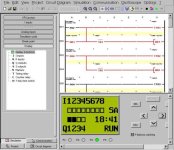
Your PicoSoft program needs to look something like the attached picture. You should add a STOP button to stop the pumps without needing to wait for the timers to run out!

David Strang's Pico Pump Control.jpg
 
Last edited:
Giday Lancie
Thank you, Your simulation runs fine P Buttons Latched.
Also runs with P Buttons not latched.
Either way the simulation runs forever.
I think my issue is line 001----P02----T01
Not sure how to change T01 to TT01.
Best Wishes
Kiwi
 
Giday Donnchadh
The PDF is just a wiring diagram as I needed help with the plc code.
And I got a brilliant reply from Lancie.
Thanks Mate
Ps What part of Ireland are you from
My Grandfather was from Cork
 
Either way the simulation runs forever.
Kiwi, If you consider 2 hours to be forever, then yes. However I tested it and it will stop each device when the timer for that device expires. You might do as I did, and try changing the timers from 2 hours to 2 minutes (or even 2 seconds) while you test it out.

Notice the difference between Rung 002 and Rung 004. Rungs 001-002 are for a non-latched momentary-contact pushbutton input. If you want this on the Pico, you probably need to use one of the I Inputs and use the Input simulator buttons instead of the P panel buttons. Using the I inputs would also allow you to have another button for a STOP input. I highly recommend that you do this, because any self-respecting PUMP program needs a good way to stop any pump at any time, and not have to wait until a timer expires.

Rungs 003-004 are for a latched or a maintained-contact input switch. The P buttons are that type, but unfortunately they also Alternate - the next P button pressed will cause the previous one to go off.
Not sure how to change T01 to TT01.
You do not need to. T01 is the output contact for Timer TT01.
 
Last edited:
Giday Lancie
I still can not set timers to time out
Simulation runs forever
I tried to attache the simulation but can not
Can I email it to you
Thankyou
Kiwi
 
Yes, you could, or I could Email my working copy to you, or better still attach my program here. (See attached ZIP file). I set this test version to have 4-second timers so you will not have to wait so long.

First, are you sure that you have the Simulator in START mode? It is not a simple process to get it to that point. Then once started, it may not be obvious to you that it is running and that the timers are running.

Question: Have you run Picosoft simulations before this, enough so that you know how to get into simulation mode?

The copy that I just posted has the timers set to seconds, not hours, so you should see the outputs go on then off. Depending on how you have the P-buttons configured (Latching or Not Latching), the Pumps should go on then off.
If you have non-latching set, then only Pump 1 will run without holding your finger on the button.

PS: Procedure to switch from Circuit Diagram mode to Simulation Mode:
(1) Click these boxes on top menu in order: "View, Simulation, Display, Display & buttons". Make sure that the Pico front-panel simulation is showing on the bottom right of your screen.
(2) Click on "Simulation, Start".
(3) Now press one of the P-buttons (^ =P2, > =P3, V =P4, < =P1). Note that you can change the P-buttons from non-latching to latching by clicking the selector box on the Pico simulated front panel.
 
Last edited:
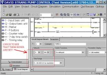
Kiwi, check to see if your timers actually have a time setting, and are set to run "S-00.000 10 ms resolution", whcich will display "SS.sss" in seconds and miliseconds. If you set the timers to H:M (Hours and Minutes), then you will not see any change in the timer until 1 minute has elapsed.

David Strang Pump Control Timer Setting.jpg
 
Giday Lancie
Thank you
The test program you emailed runs just the way I would like.
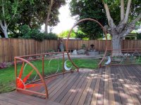
Two shots of my bonsai garden the control of witch you made possible.
Best Wishes
Kiwi.

IMG_0044x.jpg R1-13Az.jpg
 
How to add stop to timing

Giday
How to add stop to timing
Thanks
Kiwi
Attached Images
jpg.gif
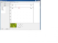
On-Time-Reset.No off when Timing.jpg (29.0 KB, 1 views)
jpg.gif
V10.jpg (180.8 KB, 1 views)
jpg.gif
V5.jpg (178.9 KB, 0 views)
 

Similar Topics

i been at this for 2 days. The code for the traffic light works great. The problem is the programming of the crosswalk button. Im so close or so...
Replies
1
Views
1,290
Dear All, I have a problem with the Simatic Timer. I'm writing a program to check the pulse signal input, if the input signal is keep changing...
Replies
12
Views
2,837
Hello everyone, I am newer on Siemens PLC 1200. From HMI, I set timer value and place in MW20(120) like 120 second How to input MW20 to timer PV...
Replies
17
Views
3,562
I did not create the program but I have a weird countdown timer problem. it is user input, say it is set for 5 minutes; it will countdown to...
Replies
9
Views
4,447
Greeatings . I have some problem whit my maschine for plastic bags . I buy maschine but i didint know is it correct. When I turn on maschine i...
Replies
2
Views
1,358
Back
Top Bottom