SLC 5/03 RTD Temp Problem

ceilingwalker

Lifetime Supporting Member
Join Date
Mar 2010
Location
Phoenix, AZ
Posts
1,586
Good day all. I have a SLC-5/03 that has in its chassis an RTD Module (1746-NR4). The system was running fine but we had to move the cabinet from its original position (about 15 feet from the tanks)to a more distant location (about 60 feet from tanks). All new wire was pulled. When I attach my RTD directly to the module it works just fine, reads 75 degrees. When I connect the RTD to the field wiring I now get a temp reading of 32 degrees. Would anyone here happen to know what might be causing this? Thank you.
 
Greetings Brent ...

did you hook it up using THREE wires – or just TWO? ...

basic idea:

the RTD works off of RESISTANCE – so when you increase the length of the connecting wires, the resistance of the wires is added to the resistance of the probe ...

so ...

more resistance makes for a lower reading ...

said another way: the input module can't tell the difference between resistance from the PROBE – and resistance from the WIRES ... in other words, "resistance" is "resistance" to the module ...

but ...

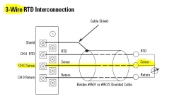
if you hook up at least THREE wires (on a module that supports that – and yours does) then the module can "read" the resistance of the wiring (out to the probe and back) and then do some internal math to "compensate" for the extra wire resistance ...

maybe that's your problem? ... with the short leads the amount of "wire" resistance wasn't a factor ... but with the new longer leads, maybe the extra resistance is adding up and messing with the reading ...

also ...

the wires need to be large enough – and all connections need to be clean and tight ...

http://literature.rockwellautomation.com/idc/groups/literature/documents/in/1746-in012_-en-p.pdf


hope this helps ...

.

RTD_sense.PNG
 
Last edited:
Greetings Brent ...

did you hook it up using THREE wires – or just TWO? ...


.

I have 3-wire RTD's and they are 22AWG. I didn't connect the shield because the last time I did, all the noise was interfering with my signal. Is there an adjustment that I must make to compensate for the longer run?
 
The "sensing" circuit of the RTD module cannot compensate for a three wire RTD circuit with an impedance higher than 25 Ω and, obviously, quadrupling the length of the field wiring run pushed your application over the threshold.
Make sure the field wiring is of a high quality and consistent impedance type (minimum Belden #9533 or equivalent)and the shield is connected on the RTD module only.
If placed within an extreme environment you might need to use Belden #83503 (or equivalent)type wiring.
 
Greetings Brent ...

did you hook it up using THREE wires – or just TWO? ...

basic idea:

the RTD works off of RESISTANCE – so when you increase the length of the connecting wires, the resistance of the wires is added to the resistance of the probe ...
That was my first thought too.
so ...

more resistance makes for a lower reading ...

Then I remembered that RTDs have a positive temperature coefficient, i.e. a higher resistance results in a higher apparent temperature.

I would investigate the 'noise' issue more closely.
 
Good day all. I have a SLC-5/03 that has in its chassis an RTD Module (1746-NR4). The system was running fine but we had to move the cabinet from its original position (about 15 feet from the tanks)to a more distant location (about 60 feet from tanks). All new wire was pulled. When I attach my RTD directly to the module it works just fine, reads 75 degrees. When I connect the RTD to the field wiring I now get a temp reading of 32 degrees. Would anyone here happen to know what might be causing this? Thank you.
Are those temperatures in F or C?

I'm a little suspicious if it is 32F. That would be 100 ohms or 0C. As you heat up the RTD does this number increase?

The module has a setting that on a broken input to set the value to zero. You could change this setting to go upscale, downscale, or invalid and see what happens.
 
Last edited:
Then I remembered that RTDs have a positive temperature coefficient, i.e. a higher resistance results in a higher apparent temperature.

well, there goes my "senior moment" analysis ... so was I thinking about a "thermistor" - or just not thinking at all? ...

(note to self: quit trying to answer the forum in between customer calls) ...
 
I didn't connect the shield because the last time I did, all the noise was interfering with my signal.
Big flashing lights and horns go off here....(n)

The shield is supposed to reduce noise, not increase it. But the shield could be connecting an ungrounded RTD to a grounded input module, and a ground potential voltage exists between the two devices. Check your grounds on both ends. Most likely your PLC does have a ground if wired according to the Allen Bradley instructions, but the RTD may not have and that would definitely create a ground loop with current flowing. In that case, try only connecting the shield to an earth ground at the PLC module end.
 
Last edited:
well, there goes my "senior moment" analysis ... so was I thinking about a "thermistor" - or just not thinking at all? ...

(note to self: quit trying to answer the forum in between customer calls) ...

Ron I always appreciate your input, senior moments and all.....
 
Big flashing lights and horns go off here....(n)

The shield is supposed to reduce noise, not increase it. But the shield could be connecting an ungrounded RTD to a grounded input module, and a ground potential voltage exists between the two devices. Check your grounds on both ends. Most likely your PLC does have a ground if wired according to the Allen Bradley instructions, but the RTD may not have and that would definitely create a ground loop with current flowing. In that case, try only connecting the shield to an earth ground at the PLC module end.

You were reading my mind. My next question was going to be, just what does the shield wire do and, if I understand you correctly, it is to keep the ground potential for the RTD's at 0 volts, yes?
 
Really strange.

If it was wired only two wire with no compensating lead, the increased lead wire resistance would make the indicated reading higher than expected, not lower.

If the AI sees a short (zero ohms), the temperature would be extremely low (way below zero), so I wonder if the configuration setting faults out at 32°F and you're looking at an accidental short in the wiring?

>The module has a setting that on a broken input to set the value to zero.
0°C = 32°F
Is the module reporting an open circuit (unreasonably high resistance) as 'zero' in degrees F?

Most shield/ground loop/common mode issues include noise. If it's a solid 32°F reading, then a ground loop leak that extracts a precise amount of DC current is a fairly low probability.
 
Last edited:
...then a ground loop leak that extracts a precise amount of DC current is a fairly low probability.
No, no. Dan, I think that you mixed the original problem with a side issue of connecting the shield causing more signal noise (than there was without the shield). Ceilingwalker did not say that with the shield there was some precise signal level - a separate problem, I think.

My next question was going to be, just what does the shield wire do and, if I understand you correctly, it is to keep the ground potential for the RTD's at 0 volts, yes?
A shield wire (really a shield cage around the two signal conductors that drains to a shield wire) is designed to electrically provide a Faraday Cage around the signal. Theoretically, any device inside a Faraday Cage is protected from any outside electromagnetic influence of any kind. (American Embassies, the CIA, and other secretive agencies build shielded Faraday cage rooms inside their buildings to conduct secret conversations and make protected phone calls.) The excess charge that accumulates on the cage needs someplace to go, and that is provided by connecting the shield wire to earth ground. Without the earth connection, the signal noise in the conductors is normally much worse. However, the shield must not be used for a ground-return path. That may be what you saw when you connected the shield, if it was connected on both ends.

Problems can occur when there are leaks in the cage. For example at the each end there has to be terminal connections that are not normally completely shielded, with 1 or 2 inches of unshielded space. I often think of a termial -block invention idea that would provide complete 100% shielding at the terminals. Someone is going to build it and make a fortune! Now is your chance, Mr. Inventor.
 
Last edited:
It turned-out to be wiring issues. After 12-hours of trying to make it work, I had a helper help me ring-out the wires. Turned-out the electricians didn't tag 6 of my 12 cables correctly!!!! We seem to have bad luck with the contractors we bring in from these projects. I don't know if it is just here in Phoenix Arizona but we have yet to have a project execute and finish without issues. Thank you all for your input.
 
It turned-out to be wiring issues.
Edward A. Murphy's Law rides again. I am glad you found the problem.

What about your shields? Did you leave them disconnected on both ends?
 

Similar Topics

If anyone has one they'd like to sell, please PM me. Alternatively, if anyone has two temperature transmitters (4-20mA), please do the same. The...
Replies
0
Views
1,288
Need a little bit of help on this one guys. I have bearing temp sensors (T/C probes) on alot of our conveyors and looking to convert all of our...
Replies
6
Views
2,819
I’m attempting to send a temperature from a SLC-5/02 to an EZiMarquee display. The vendor said to use a MSG instruction to send the data to the...
Replies
1
Views
81
Hello all. I have a few SLCs in my plant and of late we've seen a weird issue: The system will be running normally and then randomly the outputs...
Replies
2
Views
92
I am working on setting up a Prosoft Datalogger model PLX51-DLplus-232. This unit will be collecting data from a SLC 5/05 on the DB9 port set to...
Replies
3
Views
97
Back
Top Bottom