Can somebody explain what this is?

medkhai

Member
Join Date
Sep 2012
Location
bangkok
Posts
11
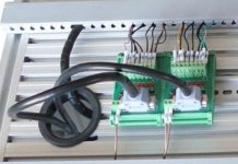
I am starting to study about PLC in my free time. I have seen this kind of connector many times, but I'm not sure what it is called, and where to buy one.

I understand usually one connects inputs and outputs to the PLC by tightening the screws on the PLC... and this seems to be some kind of interface in between.

So what's the purpose of using this?

Thank you
terminal something.jpg
 
It looks like an Input/Output card. I see nine wires, that would give you eight I/O and a common. Below that I can see what might be eight LEDs to report the status of the I/O.

The two wires on the bottom right might be power in to the card, but that doesn't explain the lack of a second wire on the left...

A part number would make this easier...
 
I Agree with rootboy, It looks like what we call in the UK a PLC breakout block, its used instead of wiring from the PLC I/O Card to terminals, it saves time with the installer connecting directly into this blocks on board terminals, and then just using the pre made lead to connect to the plc, also if you have a 32bit input moduel they can be a nightmare to hard wire and ferrule so these are used, its a labour saving device basically
 
Thanks rootboy, that was fast.
I am not trying to find out what this specific one is, just what they are, and where can i read more about them.

For example, when i google plc i/o card, the results dont seem to be talking abou these kind of cards.
Is there a couple of manufacturers websites, model names etc you can point me to. I would gladly read their manuals of datasheets, but i dont know what to search for.

Thank you again.
 
Note that these are luxury items, not required for basic PLC control. They offer faster panel assembly and optional interfacing capability for a price.
 
but as we have all got to remember is the biggest price is labour (In UK anyway) cheap components slow production down and add to overall costs, the key is good quality at affordable costs, 'Penny wise pound foolish' or 'cent wise dollar foolish' all depends on application.
 
but as we have all got to remember is the biggest price is labour (In UK anyway) cheap components slow production down and add to overall costs, the key is good quality at affordable costs, 'Penny wise pound foolish' or 'cent wise dollar foolish' all depends on application.
I agree with you in principal.
However, the more connections you have in the wiring, makes it harder to fault trace and can create future problems.
the most important thing to do is to follow the K.I.S.S. principle when designing.
If you need the 'Breakout' terminals then use them. If not, Dont use them. it is the panel designer or Equipment Specifier's call.

K.I.S.S is an all round great philosophy software and design, it's a shame not a lot of people use it, life would be so much simpler. Breakout blocks are pretty much hassle free if you install correctly its only a soldered pcb with terminals and a pre made lead, they are generally too expensive for what they are and I agree it's easier if you can actually pull on a wire or bell test to find faults
 
The breakout block can be a good asset when dealing with high-density (32-64 point card);they are available with a cable that connects directly to the I/O card face without screw terminations. This can eliminate a lot of wiring directly to the PLC chassis. For something with only 8 points, however, it probably is not that much of an advantage.
 
The two wires on the bottom right might be power in to the card, but that doesn't explain the lack of a second wire on the left...


The INPUT is the left block and OUTPUT is the right block. Most use the left / right, inputs / outputs but the input block doesn't need the +24vdc terminal but the out needs both.đź“š
 
why input card

doesn't need +24V, if not, how they lit up LED?
pls explain more.o_Oo_O
The two wires on the bottom right might be power in to the card, but that doesn't explain the lack of a second wire on the left...


The INPUT is the left block and OUTPUT is the right block. Most use the left / right, inputs / outputs but the input block doesn't need the +24vdc terminal but the out needs both.đź“š
 
There is a slight advantage to the "Remote Terminal Block" (RTB)...especially in labor costs when used with PLC I/O modules.
With I/O cable available in custom lengths, if you are using wire way you can run the cable, with the plug to attach to the I/O interface card, to the next junction box before you have to do any wiring.....plug and play.
If order it correctly...

The cable length can also be ordered, with "Fly Leads" on one end...meaning you have to wire it to the module...causing limited labor savings.
OR
Option to have the PLC I/O module terminal block supplied pre-wired to the cable.
That is how you receive the unit.
Just snap on the supplied terminal block to the PLC and connect the other end of the cable to the RTB. That is one of the reasons you can order most PLC modules with out terminal blocks, because you can order an RTB for the connections and not end up with the terminal block that came with the module.
The connections are way easier to get to on the RTB than on the PLC module. (How many doors on PLC modules do you see missing or broken from trying to get to the wiring all the time.)
An RTB used for outputs can even be ordered with fuses on board.
 
Last edited:

Similar Topics

Greetings all, I found this programs amongst the literature I kept from my first and only basic PLC class which I thought I took a few years ago...
Replies
6
Views
2,781
Can somebody please explain this to me again. I've attached a a graphic image of a proximity switch.On the image there is a load attached. What...
Replies
1
Views
1,323
While examining the STL code generated by an S7-GRAPH program I noticed the following code for handling the Supervisions. As you can see...
Replies
9
Views
3,974
I'm hoping I can get a little more info on this. My 1400 made a loud snap sound the other day after powering it up. But it seems to be working...
Replies
9
Views
2,056
So I am supposed to learn all I can about all the different PLCs, HMIs, etc we have at work. I've never used Modicon or SCADApack systems before...
Replies
1
Views
1,875
Back
Top Bottom