RIO interface configuration

Maxtronick

Member
Join Date
Mar 2013
Location
São Paulo
Posts
3
Hello.

I'm new at this forum and I have some trouble to solve.
I have here a HMI PV900 with RIO interface and I want to test this interface.
This HMI is out of it machine, so I cannot test with PLC that PV's program expects.

Then for this job I have here a allen bradley rack with a PLC 5/40 that contains RIO interface.

My problem is to configure a simple RIO network between this PLC 5/40 and PV900.
I'm new with PLC programming too, so I don't have knowledge enough for this job.
I tried to do it reading datasheet and forums.
But there's lot details to consider and I'm not getting it.

PS: My PV already has an application running and wouldn't want to change it for this test.

I hope someone help me.
 
(A) is there already a program in the PLC-5/40 – or is this a "SPARE" processor that you're allowed to use for "TESTING" purposes? ... if there is a program in the PLC then post that file (example: MAX.RSP) here to the forum ... if there is NO file already in the processor, then put one there (even if it's a "blank" file ... make sure that the processor will run without a "fault" condition popping up ... then save that file and post it here to the forum ...

(B) look on the back of the PV900 and get the Catalog number (example: 2711-XXXX) ... also get the Firmware Revision number (example: FRN 3.10) ... post these numbers here to the forum ...

(C) do you already have an existing program in the PV900? ... if you do, post that program file (example: MAX.PBA or MAX.PVA) here to the forum ...

(D) are you using a "blue-hose" cable to connect between the PV900 and the PLC-5/40? ...

note that you'll have to ZIP all of your files before you post them (forum rule) ...

remember that we can't see your system – we only know what you tell us ... the more details you give us, the more detailed our answers can be ...

in the best case scenario this would be a three minute job ... here are the basics ...

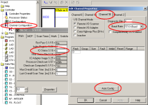
(1) set up the SPARE PLC-5/40 with an IO Status file (example: N9) ...

(2) plug the PV900 into the Channel 1B port on the front of the PLC ...

(3) go to Channel Configuration for the PLC-5/40 – and click the "Auto Config" button ... note that we might have to manually change the "Baud Rate" setting to match the PV900's rate setting ...

if all is well, the Auto Configuration feature will "find" the PV900 and tell you that the configuration was successful ...

.


RIO_auto_config.PNG
 
Sorry for late answer.

Here the informations you request.

A - It´s a spare processor and spare rack. I can do every configuration I need.
B - PV catalog number: 2711-k9A1 / Rev. C / Serie F / FRN 3.01.
C - PV has running program on it.
D - I'm using a cable that I've built. It's a two way shielded cable with one 150 ohms resistor in both side of cable.


I tried to do the procedure you described, but did not work.
When I give number 9 to field IO status S:16, the program created a data file called N9 - IOSTATS.
But when I tried to auto configure, I got a mensage saying that I did not have IO status file.

I attached all files about my system.
 
Sorry for late answer.


no problem – I've had other things to keep me out of trouble ...

A - It´s a spare processor and spare rack. I can do every configuration I need.

that's excellent news ...

B - PV catalog number: 2711-k9A1 / Rev. C / Serie F / FRN 3.01.

that matches the setup in the file you sent ... that's good ...

C - PV has running program on it.

the program that you sent is empty – which is quite alright for what you're trying to do ... I'm just wondering about where is the IOSTATUS file that should have been created ...

D - I'm using a cable that I've built. It's a two way shielded cable with one 150 ohms resistor in both side of cable.

the cable shield should be connected to the middle pin of the plugs ... if nothing else works, try swapping the wires to the "outside" pins with each other at ONE end of the cable ... how long is the cable? ... if it's just 10 feet long (or so) then the "home made" cable should work ... for a longer (or permanent) run you need to get the correct "blue hose" cable ... if nothing else works, it COULD be the improper cable that's causing your problem ...

the PV program shows that it's been set up for communications at 230.4KB ... the correct resistors for that baud rate should be 82 ohms – not the 150 ohms that you mentioned ...

here's a tip: you can PROBABLY just leave the resistors off and get away with it for a quick test ... in other words, use them if you've got them – but try communicating without them if you don't have any handy ...

I tried to do the procedure you described, but did not work.

well, you don't hit the jackpot every time ... if this was easy then everybody could do it ... I'm pretty sure that the procedure is correct – but there's something else wrong ...

When I give number 9 to field IO status S:16, the program created a data file called N9 - IOSTATS.

that sounds good ...

But when I tried to auto configure, I got a mensage saying that I did not have IO status file.

well, that could be a very good reason why the procedure didn't work ...


if you created the new IOSTAT file while OFF-line - did you then download the program to the processor? ... if it created it (as you said it did) then it should have been there for the next step ...

OR ...

are you sure that the error message didn't say this:

"AutoConfigure Unsuccessful – make sure I/O Status File Exists"

note that is NOT the same thing as saying that you do not have one ... (yes, I know that's confusing – but that's the way it works) ...

I attached all files about my system.

that's a big help ...

here's the game plan ...

(1) make sure that you're connecting the cable to the connector on the RIGHT–HAND side of the processor – at the bottom - (it's marked B) ... that would make it Channel 1B ...

(2) make sure that the I/O Status File is created – and downloaded if necessary ... the PLC program that you posted doesn't show such a file ... you said that it got created – but then where did it go? ... something's wrong there ...

(3) set the Baud Rate for 230.4 kBaud – and then hit the "Apply" button to nail that change down ...

(4) then try the Auto Config button again ...

(5) if that doesn't work – swap the wires to the two outer pins at ONE end of the cable ...

(6) now try the Auto Config button again ...

if the program file that you sent is current – then your PV should pop up as Rack 2 – Full Rack ...

good luck with it ...
 
Last edited:
Hello.

Here the news:

I've done the game plan until step 4 and it did not work.

I have created IO STATUS file after post you my PLC application data, my mistake.

But even creating it, the error message was right this: "AutoConfigure Unsuccessful – make sure I/O Status File Exists".
I thought this was because I did not have IO status file, but now I'm confused.
I have downloaded the application data and applied Baud Rate before I do AUTO CONFIGURE.

Backing to game plan, I can't move on step 5 ahead, because I did not understand what you tried to say about cable.
English is not my native language and I think was because of that.
So, I drew my cable pinout and the way I built it. Please, look at it. When you say to swap wires, did you mean " swap between white and red wire at one end " ?

I have here 82 ohms resistors. I put them.


Could you tell me if there's some calculation to do to know what resistor use with other baud rates?

Thanks to helping me.

I have attached new files (new .rsp file and cable draw).
 

Similar Topics

Can someone help me understand the difference between 1784-PKTX AND 1784-PKTXD This is the manual for both...
Replies
6
Views
3,016
I have the following equipment. 3 - thermo ramsey 2301 intergraters each with AB RIO Board installed. 1.C3 scale, 230k, Rack 1.1 2.c23b scale...
Replies
4
Views
3,685
hello, I have a problem with my AN-X2-AB-DHRIO Prosoft module, I can't connect with the module because I lost a microSD card that has firmware and...
Replies
12
Views
386
We have a remove PLC rack that is being used to collect data from older equipment via a 1756-DHRIO module. This module occasionally faults out...
Replies
1
Views
414
Does anyone have information or documentation regarding the protocol used in Rockwell's Remote IO, and how the physical layer of the network...
Replies
5
Views
929
Back
Top Bottom