Control loop from hell (and a tight budget)

DairyBoy

Member
Join Date
Jun 2007
Location
UK
Posts
393
Your comments, please...

I'm trying to control the temperature of product through a plate heat exchanger using a water tower. What could be simpler?

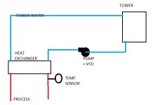
Here's the setup: The water tower is about 100m distant from the heat exch. As far as I can tell, the lag is about a minute. The temperature sensor is on the product side of the heat exch.

Now the fun part. I wasn't allowed to use an analogue output on the remote i/o for the motor controls (sorry, can't afford it) so I've made the following in the (compactlogix) plc:

HMI-entered setpoint,

HMI-entered deadband; currently set at 0.5°C (divided by 2 and placed symetrically about the setpoint),

HMI-entered time between increment/decrement fan speed pulses; currently set at 40s. The pulse length is fixed at 2s and the inverter acc/dec is set to 30s.

So, when the product temperature is outside the deadband, the inverter is nudged up or down accordingly. For the most part it finds its way into the deadband and drifts very gently up or down before being corrected again. But if the disturbance is a bit too big then it doesn't settle down but just bounces off the limits.

Am I wasting my time on this one? Should I get the sensor moved to the water at the tower instead of via 100m of pipework?

I think I know the answer.
 
Should I get the sensor moved to the water at the tower, instead of via 100m of pipework?
No, you are trying to control the product temperature at the heat exchanger, and that is where your sensor needs to be. You enter your setpoint with the HMI, but how does the temperature sensor (Process Variable) get sent to your control logic? Or is it not a sensor but just an On/Off temperature switch?

If the sensor is really an On/Off switch and you have no analog inputs, you might improve your control by using 2 temperature switches, one set to switch ON at falling temp at the deadband low temp, and the other to switch ON at rising temperature at the deadband high temperature. Then your controls try to keep the output temperature so that both switches stay OFF. Or you could use a thermostat with a built-in deadband and an anticipator circuit.

I assume that you are not using a PID block instruction. Not having the Integral term will limit the accuracy of your control. I think you could use a PID block to control the On/off time of a digital output that would simulate an analog output.
 
Last edited:
Lancie, I do at least have the luxury of a PT100 sensor, hence the ability to input setpoint and deadband. My take on a PID solution: Set a numeric ramp in the plc, compare it to the output value of the pid and I've got a variable pulse width o/p. Send that to the inverter enable i/p and apply sufficient time-constant to the acc/dec (probably short acc/longer dec) and that'll integrate the pulses to give a "pulse width to speed command" converter. How's that sound?
 
Let me make sure I understand the process here.

Is this a reasonable sketch of the process? If so then we should be able do to this just fine with a PID and provide good control.

A0402201301.jpg
 
In a nutshell, yes. But bear in mind the constraints placed on me re how I can control the speed of the fan motor: inc & dec only; no analogue o/p available.

Lancie1, rethink of the inverter acc/dec: maybe they should be equal, so it's closer to an opamp integrator.
 
Last edited:
Let me get this right. You can speed up or slow down the Pump but you do not have an Analog signals (or any serial communications with the VFD). But you do have Raise and Lower speed digital signals. ( Can't afford an AO does not compute!)

The distance to the water tower does not really matter - it is not causing a 1 min delay in the control loop.
So, Incremental PID with Gap I think it is called. Incremental because it works via Raise/Lower and Gap so you have a band where the speed is constant.
And is the flow of product through the Heat Exchanger constant? If not do you know what it is? If you do a bit of feedforward so the pump changes speed as the flow does would help.
 
In a nutshell, yes. But bear in mind the constraints placed on me re how I can control the speed of the fan motor: inc & dec only; no analogue o/p available.
That doesn't matter, we can still use PID. I've done it several times on tower fan controls.

How many increment/decrement steps do you have on the inverter?

Is there any way to maybe use three or four preset speeds instead of increment/decrement?

Are you controlling fan speed on the tower?

Or are you controlling pump speed on the tower feed water?


You might also want to review this recent discussion on using a PID for tower control. Its pretty easy to set one up. I've even used it on a system where there was no VFD, just multiple fans on across the line starters, by selecting how many fans to run based on the CV from the PID.
 
Hey, FrancisL, ( Can't afford an AO does not compute!) I couldn't agree more. It's a seven hour round trip to tweak this thing, so the profit's gone in diesel by now (y). I also agree in principle with the incremental approach but within AB it looks like it's roll your own output stage. No access to flow rate either :(
 
Tconnolly, It's fan speed that's being controlled. Pump is DOL. I've set the inverter for 20% minimum so that there's a tickover to keep some flow going. Figured that would help keep it in the active region. It's not stepped as such; just using the faster/slower inputs. I'm out of remote outputs now or the multiple presets would likely be ok.
 
The big challenge here then is that the controller doesn't really know what the fan speed is, and I'm not sure there is an accurate way to infer it with just increase and decrease speed signals.

I take it you have three signal wires then to the drive. On, Increase speed, decrease speed.

I did one tower system where there were just two DOL fans, so all I had was 0%, 50% and 100%, and still got good control. With the three wires can you configure this for OFF, 1/3 (or on at minimum speed), ~2/3 and full speed. If so then we can get you pretty darn good control. Towers are forgiving, but to have any hope of tuning it we need to know that it is really doing what we think it is doing.
 
TConnolly, That's a very optimistic reply. As far as feedback goes, I could use the "at speed" output but there's probably not much point if it's going to end up as a 3-speed setup. But why is it necessary to have speed feedback at all? Surely the only feedback is the temperature of the cooled product.
 
I don't think that the sensor location is the problem... as Lancie said, you want the sensor, at the point you want to control. The thing to realize is that their is a delay between the output change, and the PV change. The control needs to be longer than the delay. If the load is changing faster than this, then you you will have difficulty by design.

If the load is changing slowly, your control will work fine. You can't control faster than your response however. The only thing I might change, is to make the pulse width based on the error. Either two or three steps depending on how far you are from setpoint, or proportional based on error. With this, you will need to slow down as you approach setpoint.
 
Correct, the process feedback is the temperature of the cooled product and your temperature sensor is right where it needs to be. That is not the problem. The problem is that you have no way of keeping your process control element, the fan speed, under control. The only time you have positive control of the fan is when you drive it to the limits. In between, after a few bumps up and down you have no idea what is happening, and eventually the process goes out of control. Your AT SPEED indicator only tells you that the motor is turning at the speed target of the VFD, and whatever that is only the spooks know. Its like trying to drive blindfolded with someone only telling you to turn the wheel a little right or a little left and after a while you have no idea if the wheels are even straight anymore. What I'm saying is that having even just three discrete speeds to stage between is more controllable. We can then proportion the PID CV between those fan speeds to get an average cooling rate that matches the process.
 
Last edited:
Does the fan VFD support an internal PID?
This may be a route.

Easier still is to use the VFD for just a soft start and then just turn the fan on and off on a temp setpoint built with a hysteresis of about 5-10 degrees.
 
I wasn't allowed to use an analogue output on the remote i/o for the motor controls (sorry, can't afford it)

The big challenge here then is that the controller doesn't really know what the fan speed is, and I'm not sure there is an accurate way to infer it.
Does the VFD have a DeviceNet, Modbus, or Ethernet comm port and does the Compact Logic remote module? If so, you can send any and all the VFD parameters over a cheap network cable.
But why is it necessary to have speed feedback at all? Surely the only feedback is the temperature of the cooled product.
Normally your Control Variable Output would control the fan speed, and a PID would watch the Process Variable (Temperature) and adjust fan speed to make the temperature = setpoint. In this case though the speed control is crippled - no way to set speed at a certain level because you don't know where it is now - unless there is some way to get a speed feedback signal from the VFD to the Compact Logix PLC, so the PLC has a speed reference point.
 
Last edited:

Similar Topics

I have always controlled servos in Rockwell motion using position loop. I have an application where one process will push against a servo...
Replies
3
Views
262
Hello All Could we get some expertise on flow control ? -Using a PID loop in Productivity 2000 with an analog output, How can we convert...
Replies
19
Views
1,562
Hello everyone! I'm new here and this will be my first post so hopefully I can get some help, I'm having a hard time wrapping my head making some...
Replies
11
Views
4,731
So it looks like i am stuck with an old reliance DC drive on this project instead of the powerflex dc w/ 22-COMM-E. That being said i am trying to...
Replies
0
Views
1,186
Hello, I want to do a control loop, to control the density of slurry, what is the best practices in density control, and what good sensors to use...
Replies
3
Views
1,762
Back
Top Bottom