You are using an out of date browser. It may not display this or other websites correctly.
You should upgrade or use an alternative browser.
You should upgrade or use an alternative browser.
integer to 7 segment
- Thread starter roxusa
- Start date
How do I separate the integer into 1's 10's & 100's to write less program.
My display is 3 digits old school 24 vdc lamps configured with 4 lamps per segment.
I am running 503E RIO with a SN, I can fire the segments with a relay out put if needed.
My display is 3 digits old school 24 vdc lamps configured with 4 lamps per segment.
I am running 503E RIO with a SN, I can fire the segments with a relay out put if needed.
You need to write logic for a BCD to 7-segment Decoder. For each of your 3 digits, "XXX" you can have segments lit to produce numbers 0 to 9 for each of the 3 digits. So for each number, figure out which segments have to be ON, then write rung logic: IF Input 0 is equal to "1", then OTE outputs for these segments 1 to 7 needed to light up a "1". If Input 0 = "2", then turn on the segments needed to light up a "2", and so on for the 9 0-place digits. Repeat for the 10's and 100's place.
For a complete 3-digit decoder, you would need logic for each digit 0 to 9 for the 4 outputs for each digit (9 x 4) = up to 36 rung branches for each of your 3 digits, but some segments will not be lit for some digits so the total branches will be less.
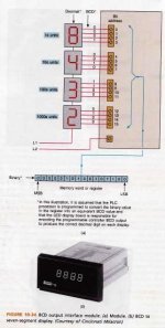
It should have 7 lamps per segment, but only 4 inputs per those 7 segments, make 1 digit from 0 to 9. Your 4 inputs to each digit should be labeled the power of 2 for that position - 0,1,2,3 (because 2^0 =1, 2^1 = 2, 2^2 = 4, and 2^3 = 8). To light up any digit, say "9", turn on bits that add up to a BCD 9 (inputs 3 and 0).My display is 3 digits old school 24 vdc lamps configured with 4 lamps per segment.
For a complete 3-digit decoder, you would need logic for each digit 0 to 9 for the 4 outputs for each digit (9 x 4) = up to 36 rung branches for each of your 3 digits, but some segments will not be lit for some digits so the total branches will be less.
Last edited:
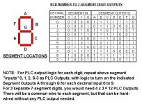
Your decoder truth table should look like this for each of the 3 digits. You need 4 PLC outputs for each digit (not counting a common wire for each digit).
Are you assuming that his BCD to 7-segment decoder is outside the PLC? I read it that he is driving lamps from PLC outputs to illuminate each segment. That would mean 7 outputs per digit.
No, I did not have to assume here, but only believe what he said:Are you assuming that his BCD to 7-segment decoder is outside the PLC?
If these were internal display LEDs, he would not be able to fire them with PLC outputs (no access to each segment). Except I think he meant 3 digits and 7 lamps per segment BUT 4 Segment Inputs per digit. He mistook the number of input terminals (4) on the digit for the number of segments.My display is 3 digits old school 24 vdc lamps configured with 4 lamps per segment. . . I can fire the segments with a relay out put if needed.
Roxusa, do you really care if your segment decoder logic is the least expensive, or do you just want to get it programmed? Does your digits turn on a segment (go high) when the inputs are high, or do the segments go low when the inputs are high (inverse logic)?
I believe that your old 7-segment display digits are old-school just like you said, and look like the ones in this picture, with 4 inputs per digit.

Last edited:
My Display is an old COPAR speed & Downtime Display.
Each of the 7 segments consists of 4-24vdc mini lamps
It displays the speed from an encoder wheel on machine and shows accumulative downtime when stopped. I wanted to write this logic into
the SLC I already have running other functions on the machine. I could run another Blue Hose up to it with Flex I/O
I have the Speed & down time already configured in the ladder in Integer File
Just not sure how to fire segments with out writing a mile of ladder logic
I am not firing a 7 segment display driver with BCD, I would like to fire them (each digit) with a 1794-ow8
Okay, I get the picture now. Each number of your display has 7 segments, but each segment is made up of four 24 VDC lamps.I am not firing a 7 segment display driver with BCD, I would like to fire them (each digit) with a 1794-ow8
No problem. Use ONE of your 1794-OW8 Outputs to turn ON/OFF ONE segment of 4 lamps. For each digit, you will need 7 OW8 Outputs. All you have to do is write logic for each set of 7 outputs, so they they work as shown in the Truth Table of my Post #5. You can ignore the "Segment IN" column and instead ONLY use the "DECIMAL NUMBER" AND the "SEGMENT OUTPUTS". For each Decimal Number, write PLC logic to produce the Segment Output. For example, suppose you assgin your first 0's place digit to your first 1794-OW8 module. (You will need a module for EACH of you display digits, with one spare output per module, unless you want to get into complicated multiplexing). You should use OW8 Outputs 0 to 6 for your first 0's-place digit segments A to G. Your logic for these 7 outputs would look like this: (later).
Last edited:
Attachments
Last edited:
I would probably save each new set of 3 digits as a String (use AIC to convert Integer to String). Then use 3 versions of the RSLogix instruction AEX, with Indexes of 1 (0's digit), 2(10's digit), or 3(100's digit), and a Number setting = 1. Pull out these 3 new extracted 1-digit strings for each digit, convert to a back to an integer number using the "ACI" instruction, then run each integer number through the 7-Segment Decoder routine, then send the chosen Output Word to the PLC output module for that number position. That's all!Still pondering how to extract the 10's and 100's digit. Thanks
AEX [String Extract]
Rockwell Software
Use the AEX instruction to create a new string by taking a portion of an existing string and linking it to a new string. Depending on the type of processor you are using you may use indexed or indirect addressing to represent addresses.
Entering Parameters
Source is the existing string. The source value is not affected by this instruction.
Index is the starting position (from 1 to 82) of the string you want to extract. (An index of 1 indicates the left-most character of the string.) This can be a word address or a decimal value.
Number is the number of characters (from 1 to 82) you want to extract, starting at the indexed position. If the index plus the number is greater than the total characters in the source string, the destination string will be the characters from the index to the end of the source string. This can be a word address or a decimal value.
Destination is the string element (ST) where you want the extracted string stored.
Operation
1 The AEX rung is enabled.
2 A specific number of characters in the source string (from Number parameter) starting from the Index character is extracted and stored in the Destination.
Last edited:
Similar Topics
Hi.
I'm using a Modbus ProSoft where I basically map data to a big INT array.
Example, where GX_I_63HPU is a REAL, MNETC.DATA.WriteData[200] an...
- Replies
- 21
- Views
- 428
Good morning all,
I'm integerating a device with a Rockwell PLC with V34 Studio 5000. The device reports error codes using a single integer to...
- Replies
- 19
- Views
- 1,286
Ex If I Read from Integer file N7:0
N7:0 is an 8 point input card , input 0 and 2 are on , rest off
When I look at :
N7:0 -7 6 5 4 3 2 1 0 I...
- Replies
- 5
- Views
- 742
The analog array has 16 individual bits and each bit is an alarm.
SCADA is having issues getting the BIT bool value.
However they can get the...
- Replies
- 9
- Views
- 1,020
I set up a Mitisubishi test system on the bench.
Q03UDSPU
Q173DCPU
MR-J3-40B
HF-KP43
HMI is a LS XP50 TTA/KP43
I am trying to use a signed...
- Replies
- 1
- Views
- 394


