Analog output ? problem siemens s200

rbduck1

Member
Join Date
Mar 2013
Location
East Tennessee
Posts
19
Good day guys (and gals) I have a question about what is required to get an analog output from a em232 analog output module connected to an s200 siemens cpu. I am fairly new to s200 progamming, but not new to troubleshooting.

I have a test cpu set up with a simple program loaded to test the analog output card. I have a signal enabling the card. I have it set for zero volts at 0 and 10 volts at 32000. I can't seem to get any voltage at the output. The analog output card is brand new. WHat could I possible be doing wrong?
 
Have you connected a 24V supply to the Analog expansion unit? Is the green light illuminated on the Analog expansion unit?
 
I appreciate the reply. Yes, I have 24v to the expansion module. The green light is on. Does there need to be a resistive load across the voltage output terminals in order to actually have output and actually see a voltage?

I also have an input enabling the output in the software. At least, I hope it's correct.

I'm catching on to this pretty quick, but I've found many small things I'm doing incorrectly.
 
Last edited:
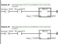
If you MOVE a Word to the analog output you should get a voltage, it you were to use the current output then you would need a load. If you have a supply to the expansion unit the next most probable fault is that you are using the wrong analog address. Typically you are should be using AQW0 or if the PLC is an S7-224XP which has onboard analog outputs then you would use AQW4.

You don't need an input to enable the analog output.

If that doesn't solve the problem then post the code and hopefully I should be able to spot the problem.

I assume that you have connected the ribbon cable between the PLC and expansion unit.
 
I love it when the lights go on (in my head). Let me give a little background. These questions are a result of a problem I'm having with a piece of equipment that keeps blowing analog expansion units. I'm also using the problem as a training exercise. I discovered today that the board that the analog output feeds is backfeeding and burning the outputs. To test the expansion units, I have been connecting them to another test cpu. I surmise from the replay from you, I have discovered why I can't get the analog unit to produce a voltage output. Back to the original question.

I'm not at work right now. I believe that the cpu I'm testing with is an S7-224XP. The cpu in the machine is all digital in/out. I did notice that the expansion module starts with AQW4 and not AQW0 the Machine cpu uses. I'm not sure what syntax (if that's the correct verbage) to use in the data block to address the analog output to AQW4.

I hope I didn't confuse anything. I''l get back tomorrow morning. Thanks again for the help.
 
Here is an example of the analog out method. You can see that this software can run on either an S7-224XP or S7-226 depending on the selection of M27.5. Ignore M15.6.

If you are having problems with output being blown it is most likely because the negatives are at different potentials. The safest way is to add an isolator, something like this:

http://www.status.co.uk/product/175...age-process-signal-isolator-_-condtioner.html

Siemens Analog Out.jpg
 
I concur with BryanG's recommendation to implement an isolation transmitter. The device that you are attempting to control apparently features a non-isolated analog input. It's relatively unusual to encounter that issue with modern electronic equipment, but it used to be a fairly common problem, back in "the day".
 
I have thought of the isolator, but did not know if there was anything like that available. I am proceeding that direction. Also, this machine was probably built back in "the day".
I'm not surprised at anything I run across here.

My question on the programming of an analog output is probably something simple and straightforward. I just need help seeing the obvious. I'm looking in the data block. I know what some of the values mean. I don't know what all of them are or do. If you could give me a quick meaning I can probably understand better . Here is what I'm seeing.
I know what the "running speeds" are. I don't know what the VWxxxxx values mean.

//
//DATA PAGE COMMENTS
//
//Press F1 for help and example data page
//
Rev_Spd_Setup:VW2000 -8000
Fwd_Spd_Setup:VW2002 8000
Cutter_Speed:VW2004 32000
Fwd_Spd_Running:VW2006 19000
Rev_Spd_Running:VW2008 -14500
Thumb_Pressed_Time:VW2010 4
Top_Cyl_Dn_Time:VW2012 2
Top_Cyl_Safety_Time:VW2014 4
Side_Cyl_Safety_Time:VW2016 2
Start_Rev_Cycle_Time:VW2018 4
VW2020 4
VW2022 1
VW2024 0
VW2026 0
VW2028 0
 
VWxxxx is a memory location that is Word length (16 bit). Variable Word 2000.

VD would be a Variable that is Double Word length (32 bit).

VB would be a variable that is Byte length (8 bit)

Unlike some PLCs the variable location doesn't define the type of data stored in it. So a VD memory location might hold a Double Integer or a Real (Float) value (both 32 bit), it is up to the programmer to know what is stored in a location.

Rev_Spd_Setup:VW2000 -8000
This line sets Variable Word 2000 to a value of -8000

One final thing, the values in the Data Block definition are only used if the Super Capacitor or back up battery ran out of charge. Otherwise the current value in the memory location is used.
 
OK, how do I set the output location for the analog out. I'm talking about the AQW0 or AQW4. I am using the CPU 224xp which has integrated analog outputs.
 
Don't really understand the question, but....

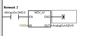
.... to put a fixed value in to an analog output, go in the Program Block section of the software rather than the Data Block. The below should give you about half scale 5V if the analog unit is set for 0-10V. I guess you might be able to do this in the Data Block something like : Analog_out: AQW4 16000 but of course you never want a fixed value on an analog output so it wouldn't make sense.

Simple Analog Out.jpg
 
Bryan, I apologize. The question was a duh moment for me. Sometimes I get thinking too hard and the simple things escape me. I realized that the output tag ID (if that's correct verbage) is the address. I'm sorry for the confusion. I am learning quite a bit from this exercise.

I do understand what you are saying in the previous reply
 
No problem. I am very much where you are at but with the S7-200 successor, the S7-1200. Getting very frustrated and about the throw the full kit out the window.
 
Like you . I'm very frustrated. I've discovered, that somehow, the main S7-200 cpu is causing the EM-232 analog expansion modules to fail. I can connect a new one with only 24 volts and the main cpu connected and nothing else, the module will go defective. I'm scratching my head on that one.

I may have more questions. I really do appreciate your help. The only other PLC's I've had any experience with were Texas Instruments. That was back in the 1990's I was in telecommunications for 10 years. Now, I'm back at PLC's. I'm learning and re-learning. It's a struggle I'm getting too old for. Thanks again.
 

Similar Topics

Hi We're having issues with an FX1N-1DA-BD Analog output module. We're using an metallic contamination sensor MCS 1000 to detect particles. This...
Replies
1
Views
105
Hi, I tried today to get RD3A and WR3A instructions to work on the PLC and it didn't work, but it worked in simulation. I followed the clone...
Replies
18
Views
1,396
Hello All!! I am new to the forum and have seen alot of good answers so far, but I have not been able to resolve the issue I am having. :mddr...
Replies
9
Views
4,263
Dear friends, Presently I am working in a water treatment plant where T&C is going on, we are using VFD to control motors while...
Replies
10
Views
7,981
Good day guys (and gals) I have a question about what is required to get an analog output from a em232 analog output module connected to an s200...
Replies
0
Views
2,576
Back
Top Bottom