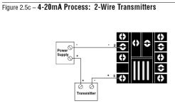
4-20mA Trasmitter schematic

Adam303

Lifetime Supporting Member
Join Date
Aug 2009
Location
Chicago
Posts
587
Hello friends,

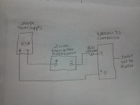
I have run into some issues with a process controller ( WATLOW SERIES 93 P/N 93BA1CC000AM). This controllers is set to receive 4-20mA input, the transmitter is a two wire 4-20 output (Honeywell SPTma0100PA4B). Attached is a schematic that I’m trying to figure out especially why would someone put in a 100 ohm ¼ resistor on the feedback line, it does not make any sense to me. Can anyone help out. The system has been setup like this for a while now and one of the plant electricians is telling me that they have replaced a dozen of these transmitters in the past year and a half. The pressure transmitter is reading pump discharge pressure. Can help out. Thank you in advance.
IMG_20130418_221544.jpg
 
Last edited:
It may be there for testing. To develop a voltage if the input resistance on the controller is very low. If you have the manual take a look.
 
Thanks Mickey,
I did check the manual and I can’t find anything that states about installing a resistor in line. Only when calibrating the output side of the controllers 4-20mA but that’s not the case. This unit has three Watlow controllers setup with the 100 ohm resistor all identical.
The drawing that I posted is what I copied off the original schematic, I don’t think that anyone would place the resistor on the schematic if it only wore for testing.
 
Last edited:
I'm not subjecting the manual would tell you to put a 100 ohm resistor in series with the load. What I'm saying is the load may be to low to test the circuit without breaking the circuit to measure the current. Sometimes you can just measure across the load if it has say a 250 ohms which would give you 1 to 5 volts.

The manual you posted says the input resistance is 5 ohms ( kind of small ) that would be .05 to .1 volts, 100 ohms would be .4 to 2 volts.

I can't think of any other reason to do it.
A Hart communicator needs 250 ohms, you may get away with 105 ohms, I have never tried it.

5ohmsload.png
 
My first question was 'is the transmitter isolated', but I found a manual and the answer is 'Yes'.

Manual:
http://sensing.honeywell.com/index.php?ci_id=51401

One thing that did stand out in the manual is on page 4,
Figure 2. SPT mA Version External Load Line. I read that as being, for a 24V power supply the sensor needs something like a 500-600ohm load, you only seem to have a 105ohm load. Maybe you could replace the 100 ohm resistor with a 600 ohm resistor and see if it fixes the problem.

Also looking at that graph you can make a guess where someone choose the 100ohm from.
 
Last edited:
One thing that did stand out in the manual is on page 4,
Figure 2. SPT mA Version External Load Line. I read that as being, for a 24V power supply the sensor needs something like a 500-600ohm load, you only seem to have a 105ohm load. Maybe you could replace the 100 ohm resistor with a 600 ohm resistor and see if it fixes the problem.

Also looking at that graph you can make a guess where someone choose the 100ohm from.

Bryan this is not minimal load but maximal load according to powersupply voltage...to generate 20mA on the whole circuit with internal device under the ''ohm law'' you either need more voltage or less resistance this is it.
Adding more load to the sensors won't help. Most of them could be sorted with just multimeter internal resistance and work just fine...

In the drawing, the + of the ps is going to the minus of the device....it's doesn't look good...+24vdc must goto sensor positive input while sensor negative output must go to the plc positive input and plc negative input to the 24vdc return
 
I did indeed read it backwards, but.... Pressure sensors with an isolated output are generally very robust. They are typically damaged by shock changes to the measured pressure which is beyond the sensor limit. They can also be damaged by electrical interference and over-volt or electrical spikes. I haven't blown any up by connecting them backwards, it just tends to just give a false fixed reading or no reading at all. If the device is happy up to 600ohm and you only have 105ohm currently in circuit, it is the easiest possible fix to try increasing that resistance.
 
Hello friends,

I have run into some issues with a process controller ( WATLOW SERIES 93 P/N 93BA1CC000AM). This controllers is set to receive 4-20mA input, the transmitter is a two wire 4-20 output (Honeywell SPTma0100PA4B). Attached is a schematic that I’m trying to figure out especially why would someone put in a 100 ohm ¼ resistor on the feedback line, it does not make any sense to me. Can anyone help out. The system has been setup like this for a while now and one of the plant electricians is telling me that they have replaced a dozen of these transmitters in the past year and a half. The pressure transmitter is reading pump discharge pressure. Can help out. Thank you in advance.

I don't know what the resistance is on the Watlow Controller. As you know, many controllers or input devices use a 250 OHM resister for 4-20 mA.

Having said that, the Honeywell Smart Transmitters require a minimum loop resistance for the communicator to talk to the transmitter. I believe the minimum is 100 ohms. So if the Watlow controller doesn't use a 250 ohm resister, then the resister was probably included so that the Honeywell Communicator could talk to the transmitter for configuration and calibration.

On an aside, the wiring of that 2-wire loop is backwards from everything I have ever done.

I have always wired as follows (+) on PS to (+) on Transmitter. Then (-) on Transmitter to (+) on Controller or Input then (-) on Controller to (-) on PS. At least to me, this is more logical, but I'm sure others would disagree.
 
I think the Watlow Series 93 User Manual wiring is like most of us would think it should be (different than Adam303's sketch). If the 100 Ohm resistor is needed for some reason, I think it should be wired between Transmitter (-) and Watlow (+) on Terminal 5.

Watlow 4-20 mA Transmitter Wiring.JPG
 
Last edited:
I agree with JHarbin, the 100 ohm resistor adds enough loop resistance to let a HART communicator talk to the transmitter.

On an aside, the wiring of that 2-wire loop is backwards from everything I have ever done.

Not only backwards, but dysfunctional. The drawing does not represent the all devices' polarities correctly.

At lease one of the devices has its polarity reversed from that shown in the drawing.
 
I agree with JHarbin, the 100 ohm resistor adds enough loop resistance to let a HART communicator talk to the transmitter.


Not only backwards, but dysfunctional. The drawing does not represent the all devices' polarities correctly.

At lease one of the devices has its polarity reversed from that shown in the drawing.

Just for clarification, the resistor is not only HART communicator, but also the Honeywell DE Communicator.
 
At lease one of the devices has its polarity reversed from that shown in the drawing.
Bingo. In Adam's sketch, the current would be trying to flow through the transmitter from - to + instead of the conventional + to - direction. If the transmitter terminals were reversed, the unconventional circuit might even work!
 
Last edited:
adam the + and - are not correct.
you can leave the 100 ohm in to check with a voltmeter, however it is not needed, it is good practice to avoid shortcircuit. now max is 0.24 amps.
from power supply + to + of transmitter then the - should go to the + of the input board. the - of the input back to power supply -
 
I would remove the 100 ohm resistor and put a 250 OHM across the input to convert to 1-5 V.
Then use the Watlow 0-5 Volt range and set the zero and span to compensate for the missing volt.

For example 4-20 ma = 0-100 psi, Watlow instrument 4-20 ma display range is zero = 0 and span = 100.
After conversion to 1-5 volts, each volt represents 25 psi (100/4).
You will configure the Watlow instrument to use 0-5 V range and zero and span will now set at 0 = -25 psi and span = 100 psi. Then 1 volt will then be 0 psi.

..
 

Similar Topics

Hi all, I'm connecting several 4-20mA sensors together in parallel (only one shown below) The enclosure is ABS plastic with metal backplate DAQ...
Replies
5
Views
262
Problem: Our PLC can only output 4-20mA, but the actuators it needs to control, modulate based on a 0-135Ohm signal. Buying 4 or 8 individual...
Replies
7
Views
268
What's your go to 4-20ma isolator. I've got some 4 wire 4-20ma from several flow meters and scales that I would like to isolate before it gets to...
Replies
10
Views
1,679
Hi, I need to read three 4-20mA signals from a DCS(ABB) in a remote 6 channel analog input module with RS485 modbus port. When I connected...
Replies
2
Views
480
Hello this is my first post. Looking forward to being more involved in this community to learn and hopefully help others. Any help or guidance...
Replies
7
Views
783
Back
Top Bottom