You are using an out of date browser. It may not display this or other websites correctly.
You should upgrade or use an alternative browser.
You should upgrade or use an alternative browser.
A beginner problem with the latch
- Thread starter alyelhefni
- Start date
Alyelhefni,
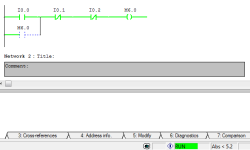
The logic that you show does not use a Latch instruction, but instead trys to use a seal-in method to keep M6.0 ON or sealed in, once it has been turned on by I0.0
However the dashed lines at | |--- seem to indicate that there is a problem with your logic. It could be that the dashed line indicates that there is a missing connection at this point. Maybe you need to draw in that line to complete the circuit.
On the other hand, coud the program error handler be trying to show that M6.0 is being turned OFF somewhere else?
The logic that you show does not use a Latch instruction, but instead trys to use a seal-in method to keep M6.0 ON or sealed in, once it has been turned on by I0.0
                            M6.0

                            | |---
However the dashed lines at | |--- seem to indicate that there is a problem with your logic. It could be that the dashed line indicates that there is a missing connection at this point. Maybe you need to draw in that line to complete the circuit.
On the other hand, coud the program error handler be trying to show that M6.0 is being turned OFF somewhere else?
Last edited:
alyelhefni
Member
OP
I've kept trying various things and I came up with a partial solution to the problem :
The program works when I use memory bit of 124.1 124.2 124.3 .... etc
I don't know why 6.0,1,2,...etc and 1.0,1,2....etc are "bad" and 124.number is accepted
There must be a method where I assign or declare memory bits numbers or names I want
but I cant find that >>> I'm using siemens symatic manager s7 if anyone could help
Different models of PLCs have different amounts of memory in different locations. You cannot AssUMe that all memory locations are available for all instructions in all models of the Siemens S7 PLCs.I don't know why 6.0,1,2,...etc and 1.0,1,2....etc are "bad" and 124.number is accepted.
What model of Siemens PLC do you have selected for your program to control?
In general, the "I" memory type is reserved for Siemens PLC Inputs, which are very limited in number, and depend totally on the model of PLC. Some have fewer, some have more Inputs. The "M" type of memory is usually for internal relays and flag bits. In Siemens, Outputs are often the "Q" memory type. Check your manual for your model number to see what memory areas are available for each type. It may be difficult to find the right Siemens manual that will show what you need to know.
Last edited:
cbuysse
Member
I only have limited experience with Siemens S7 programming myself, but my first thought is that maybe you've used the 6.0 memory address elsewhere in the program. Don't forget to check for MW 6 or MB 6.
Right click on the tag and select "Goto" -> "Location" this will pull up the cross reference data for that memory bit. In the lower left corner of the box I believe there is a check box for "Overlapping memory locations" this will show you if this bit is used in another location as a byte / word / dword etc..
alyelhefni
Member
OP
Well this haven't solved the problem yet
I made a simple exercise to spot out the problem
please check the 2 cases in the following pictures
the whole program is those 3 branches
figure 1
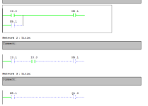
figure 2
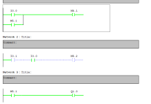
it's obvious that the memory bit here turns zero if it's located as an output in other branches and it doesn't get a one , it kinda resets it self to zero again
thats really frustrating because like this its impossible to get back to a certain state after leaving it
how can I solve this ?
I made a simple exercise to spot out the problem
please check the 2 cases in the following pictures
the whole program is those 3 branches
figure 1

figure 2

it's obvious that the memory bit here turns zero if it's located as an output in other branches and it doesn't get a one , it kinda resets it self to zero again
thats really frustrating because like this its impossible to get back to a certain state after leaving it
how can I solve this ?
bernie_carlton
Lifetime Supporting Member + Moderator
It looks like the double output syndrome. DO NOT use as an output ( ) an address in more than one place. The last rung which has the bit as an output 'wins'. Its logical truth is the last one applied before the rung which uses a contact of that bit. If you feel you need to use complex rungs combine the logic to drive just one instance of the output bit.
alyelhefni
Member
OP
I've understood that now that for a single address output the last always wins
and therefore I shouldn't include same address as an output in more than one place
That really explains why the program wasn't working well
But I really can't figure another way to get back to old states
meaning
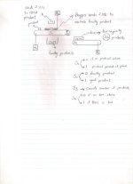
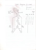
for example : I push the start button and motor1 runs while motor 2 is off.... so this is state 1
and then when a sensor gives 1 motor 1 stops and motor 2 starts working .... and that is state 2
when sensor 2 gives one stop motor 2 and run motor 1 ..... and that is the original first state (state 1)
so how can I write such a ladder diagram without repeating same addressed outputs ?
harryting
Lifetime Supporting Member
You are jumping over the states all together.
Let's think about this. Say you want to water the lawn on Monday and prune the tree on Tuesday. Do you have any problem doing that? No. Because your calendar tells you what day it is.
You need something to keep track of the day, or in this case, the state. As always i would suggest new programmer to write in pseudo code rather jump right into ladder logic. In pseudo code:
If State1=true then turn on pump1 AND turn off pump2
If State2=true then turn off pump1 AND turn on pump2
Then you have separate logic (calendar?) to keep track of the state (day):
If Button=true then state1=false, state2=true
Now, there's a hundred different way you can keep track of states. You can find some of those by search for "sequencer". You can use an interger, for example, State=1,2,3.4.... and so on
I will be happy to help but right now, I'm just trying to understand what you actually want the program to do.I've understood that now that for a single address output the last always wins
and therefore I shouldn't include same address as an output in more than one place
That really explains why the program wasn't working well
But I really can't figure another way to get back to old states
meaning
for example : I push the start button and motor1 runs while motor 2 is off.... so this is state 1
and then when a sensor gives 1 motor 1 stops and motor 2 starts working .... and that is state 2
when sensor 2 gives one stop motor 2 and run motor 1 ..... and that is the original first state (state 1)
so how can I write such a ladder diagram without repeating same addressed outputs ?
Here is a short list of questions.
What causes the sensors to change state?
When do the sensors change state?
Are they floats on a tank or something else?
Is motor 1 and motor 2 pump motors or something else?
What condition do you want to stop the motors?
After both have run or just at any time?
Last edited:
alyelhefni
Member
OP
alyelhefni
Member
OP
bloodredsoul
Member
could you gimme a download link for your version of the program? i will come up with a simple ladder diagram for you as reference for how yours should look like
Similar Topics
I am trying to connect to SLC5/03 using an FTDI usb to rs232 with female to female converter at 1 end... however I can not connect to it ... the...
- Replies
- 8
- Views
- 1,266
Hi,
Sorry for my bad english, I'm from Poland.
I've decided to learn basic PLC programming as hobby and to maybe get a better job. I have...
- Replies
- 2
- Views
- 1,329
I'm trying to teach myself how to use factorytalk so I can add buttons, screens and other cool junk and am having trouble testing my application...
- Replies
- 2
- Views
- 1,908
Hello everyone, I am a very basic beginner of PLC; I am currently in a class where we are going over PLCs. We have to complete Programmable Logic...
- Replies
- 7
- Views
- 2,843
hello , everybody , i just begin to learn how to program for the mitubishi plc. following is the program for control the speed of pump.
who can...
- Replies
- 3
- Views
- 5,830


