Forces in Allen-Bradley – more than you really wanted to know

Ron Beaufort

Lifetime Supporting Member
Join Date
Jul 2002
Location
Charleston, SC
Posts
5,701
"forces" sound like such a simple idea – just temporarily MAKE something in the PLC do whatever you want it to do ...

but like most other "simple" things, forces can actually be quite confusing – even to technicians and programmers who have years of experience ...

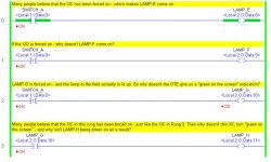
the screen shot below was taken from a 1756-L55 ControlLogix processor running RSLogix5000 version 16.03 software ... only one real-world switch and four real-world lamps were used ... this discussion will focus ONLY on the way that Allen-Bradley systems implement forces ... other PLC brands use different methods ...

the examples shown below were chosen to demonstrate some of the most confusing aspects of forces ...

the questions in the rung comments are quite simple – but most people have a difficult time answering them ... other posts in this thread will offer a "nuts-and-bolts" explanation of how these forces ARE (and are NOT) affecting the operation of the system ...

.


forces_intro.jpg
 

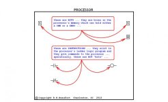
(1) let's start the discussion with a few critical definitions ...

(2) a "BIT" is a "BOX" ... it is a box located in the processor's memory – and the box can hold either a ONE or a ZERO ...

(3) it's also critically important to know what a "bit" is NOT ... specifically, a bit is NOT an XIC, an XIO, an OTE – or any of the other little doodads located in the rungs of the ladder logic program ...

(4) "INSTRUCTIONS" are the XIC, XIO, OTE and other little doodads which appear in the rungs of the ladder logic program ...

(5) it's also critically important to know what an instruction is NOT ... specifically, an instruction should NOT be called a "bit" – although many technicians, programmers, and authors do indeed call it that ... this mistaken terminology is incredibly confusing – especially when it comes time to talk about "forces" ...

(6) if you're looking for the "secret handshake" on forces then here it is:
in an Allen-Bradley system you do NOT force "bits" – and you do NOT force "instructions" ...

in an Allen-Bradley system, the forces are applied to the FIELD SIGNALS coming INTO – and going OUT OF the processor ...

(7) that rule explains why only INPUTS and OUTPUTS can be forced with an Allen-Bradley system ... specifically, "internal" bits/boxes can NOT be forced - simply because "internal" bits/boxes do not have field signals COMING IN – or GOING OUT of the processor ...

(8) note that in some OTHER brands of PLCs you DO indeed force their bits/boxes – but NOT in an Allen-Bradley system ...

(9) just for completeness, we can also consider tags which are PRODUCED or CONSUMED as capable of being forced ... the "field device" in this case is something like another processor – but the concepts of INPUT and OUTPUT signals still apply for the purposes of our discussion ...

(10) just for discussion, I personally do not like the term "internal bit" ... mainly because ALL bits/boxes are "internal" – specifically, ALL bits/boxes are located internally ("inside") the processor ... but we still need SOME terminology to differentiate between bits/boxes which DO have field input or field output signals – and other bits/boxes which do NOT have input or output signals ... so let's just stick with the term "internal bits" for the HAVE NOTs – and move on ...

(11) the next post will dig into the nuts-and-bolts of Allen-Bradley forces – but first let's set our sights on a few common misconceptions ... and remember that we're talking ONLY about Allen-Bradley systems here ...

(12) suppose that we hear someone say: "Force that OTE on" - or "Force that OTE off" ... that's a misconception – it's WRONG – and it's confusing ...

(13) suppose that we hear someone say: "Force that BIT on" - or "Force that BIT off" ... that's a misconception – it's WRONG – and it's confusing ...

(14) suppose that we hear someone say, "Force that XIO on" - or "Force that XIO off" ... that's a misconception – it's WRONG – and as you'll see below, this particular example can be extremely confusing ...

(15) now suppose that we hear someone say, "Force that XIC on" - or "Force that XIC off" ... technically this is a misconception too – it's WRONG ... but ... in this particular situation, the force will usually have exactly the intended effect – so most people ignore the technicalities and get on with their lives ...

(16) and now a warning ... if you do not intend to accept (and abide by) the definitions that I've just laid out, then you might as well skip the rest of this thread ... frankly the explanations offered below will not make sense to you – and you'll be wasting your time to read them ...

(17) and keep in mind while reading, that you don't have to take my word for any of this material ... just hook up some switches and lamps to a PLC and try these experiments out for yourself ...

.

bits_and_instructions.jpg
 
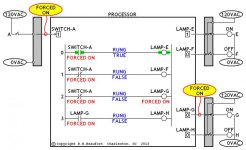
(18) the figure below widens our horizons beyond the PLC ladder program – and shows the connections to the field devices that we've been discussing ... I've taken a few minor liberties with the display – such as indicating "FORCE ON" instead of just "ON" ... this is just to make it easier for our discussion ...

(19) notice the yellow balloon indicating that SWITCH-A is being forced ON ... it is critical that you notice that the force is being applied to the field signal (the ARROW) which takes the signal from the input module and carries it into the bit/box inside the processor ... specifically notice that the force is NOT applied to the bit/box itself – but rather the force "overrides the field signal" going into the bit/box ...

(20) next notice the yellow balloon indicating that LAMP-G is being forced ON ... it is critical that you notice that the force is being applied to the field signal (the ARROW) which takes the signal from the bit/box and carries it over to the output module ... specifically notice that the force is NOT applied to the bit/box itself – but rather the force "overrides the field signal" being sent to the output module ...

(21) now let's work through a scan cycle and see what's happening "under the hood" ...

(22) SWITCH-A is open – and there is no current flowing through the input field circuit ... normally this would result in a status of ZERO in the bit/box for SWITCH-A ... but since we have a "FORCE ON" applied to SWITCH-A, then the bit/box contains a status of ONE ... this makes perfect sense to most people ...

(23) on rung 0, the XIC instruction tells the processor to "go look for a one" in the bit/box for SWITCH-A ... the processor DOES find a one – so the processor evaluates the XIC as TRUE ... this results in TRUE logic for the rung ...

(24) don't miss the fact that having SWITCH-A denoted as "FORCED ON" on the computer screen has NOTHING to do with the TRUE status of the XIC ... specifically, the "FORCED ON" legend is merely telling us that the field signal from SWITCH-A is being forced on ... more specifically, the "FORCED ON" legend is NOT telling us that the XIC is being forced either "on" - or "true" ...

(25) this is hard for most people to accept ... seeing the XIC shown as "green on the screen" certainly SEEMS to indicate that the XIC instruction is being forced on – but that is NOT what is happening here ... we'll prove this critical concept in the following rungs ...

(26) but to finish up with rung 0, when the TRUE rung condition reaches the OTE for LAMP-E, the OTE instruction tells the processor to "go write a one" into the bit/box for LAMP-E ...

.

force_locations_ac.jpg
 
Last edited:

(27) on rung 1, the XIO instruction tells the processor to "go look for a zero" in the bit/box for SWITCH-A ... the processor does NOT find a zero – so the processor evaluates the XIO as FALSE ... this results in FALSE logic for the rung ...

(28) don't miss the fact that having SWITCH-A denoted as "FORCED ON" on the computer screen does NOT have the effect of making the XIO instruction either ON – or TRUE ... specifically, once again, the "FORCED ON" legend is merely telling us that the field signal from SWITCH-A is being forced on ... more specifically, the "FORCED ON" legend is NOT telling us that the XIO will be evaluated as "on" or "true" ...

(29) this is very hard for most people to accept ... a frequent question is: "But if I've forced it on, why isn't it true?" ... the reason for their confusion is that the "FORCED ON" legend on the screen does NOT refer to the status of the instruction (the XIO) that they're pointing to ... specifically, the "FORCED ON" legend on the screen ONLY tells us that the field signal from SWITCH-A is being forced on ...

(30) here's another "secret-handshake" ... whenever you Right-Click on any instruction to install a "FORCE" – you are NOT selecting the instruction (the XIC, XIO, OTE, etc.) ... instead ALL that you are doing (I repeat ALL that you are doing) is selecting the ADDRESS associated with the instruction ... by selecting the address (for example: SWITCH-A) you are telling the RSLogix software which FIELD SIGNAL you want to force ...

(31) earlier I pointed out that sometimes people will say: "Force that OTE" or "Force that XIO" ... those statements are misconceptions – they are WRONG – and they are confusing ...

(32) to nail this idea home, consider that it makes ABSOLUTELY NO DIFFERENCE whether the instruction that you Right-Click when forcing happens to be an XIC, an XIO, an OTE, an OTL, or an OTU instruction ... as long as the ADDRESS over the instruction remains the same, you'll get EXACTLY the same results each and every time you force ANY of those various types of instructions ...

(33) here's a "weird" demonstration to prove the point ... you can even force an ONS (One Shot) instruction – as long as you give it a valid INPUT or OUTPUT address ... now the One Shot might not work correctly – but the fact that you can apparently "force" the One Shot is another indication that it's actually the ADDRESS that's being selected by the Right-Click ... specifically, it is NOT the type of instruction that determines either HOW - or WHERE - the force will be applied ...

(34) the "take away" from this part of the discussion is that we NEVER force INSTRUCTIONS ... instead we only force FIELD SIGNALS – either incoming field signals – or outgoing field signals – but NEVER instructions ...

(35) now to finish up with rung 1, when the FALSE rung condition reaches the OTE for LAMP-F, the OTE instruction tells the processor to "go write a zero" into the bit/box for LAMP-F ...

(36) on rung 2, the XIO instruction tells the processor to "go look for a zero" in the bit/box for SWITCH-A ... the processor does NOT find a zero – so the processor evaluates the XIO as FALSE ... this results in FALSE logic for the rung ...

(37) as on rung 1, having SWITCH-A denoted as "FORCED ON" on the computer screen does NOT affect whether the XIO instruction will be evaluated as either TRUE or FALSE ...

(38) continuing right along with rung 2, when the FALSE rung condition reaches the OTE for LAMP-G, the OTE instruction tells the processor to "go write a zero" into the bit/box for LAMP-G ...

(39) do not be misled by the "FORCED ON" legend under the OTE for LAMP-G ... that has NOTHING to do with the fact that the processor will obey its ladder logic program (NOT the force) and will definitely "go write a zero" into the LAMP-G bit/box precisely as the ladder logic dictates ...

(40) and if you're a big fan of "green on the screen" indications, you're about to be sorely disappointed by the display of the OTE for LAMP-G ... notice that even though the FIELD DEVICE (the actual lamp in the field) is being driven ON, the OTE does NOT indicate a "green on the screen" condition ... that's simply because the bit/box contains a status of ZERO - and not a status of ONE ...

(41) this is hard for most people to accept ... a frequent question is: "But if I've forced the lamp on, why isn't it turning on?" ... here the lamp (the device located in the field) actually IS being "turned on" ... but "green on the screen" indications can be misleading because they NEVER relate directly to the status of the field devices ... instead these indications are a result of what status the RSLogix5000 software "sees" in the bit/boxes ...

(42) since the bit/box in this case contains a status of zero, the software is showing the OTE without a "green on the screen" highlight ...

(43) another frequent question is: "But if I've forced the OTE on, why doesn't it go write a ONE into the bit/box?" ... the answer is that the OTE was NOT actually forced in the first place ... instead, the ADDRESS for LAMP-G was selected – and so the force operation was actually applied to the FIELD SIGNAL for LAMP-G ... the field signal is DOWNSTREAM of the bit/box – so the bit/box does NOT change state to reflect the force ...

(44) on rung 3, the XIC instruction tells the processor to "go look for a one" in the bit/box for LAMP-G ... the processor does NOT find a one – so the processor evaluates the XIC as FALSE ... this results in FALSE logic for the rung ...

(45) don't miss the fact that having LAMP-G denoted as "FORCED ON" on the computer screen has NOTHING to do with the TRUE or FALSE status of the XIC ... specifically, the "FORCED ON" legend is merely telling us that the field signal to LAMP-G is being forced on ... more specifically, the "FORCED ON" legend is NOT telling us that the XIC (the instruction) is being forced either "on" - or "true" ...

(46) this is another hard idea for most people to accept ... seeing the XIC marked "FORCED ON" on the screen SEEMS to indicate that the XIC instruction is being forced on – but that is NOT what is happening here ... this is yet another indication that the instructions (XIC, XIO, etc.) in the ladder logic are NOT being "forced" ...

(47) and to finish up with rung 3, when the FALSE rung condition reaches the OTE for LAMP-H, the OTE instruction tells the processor to "go write a zero" into the bit/box for LAMP-H ...
 
Last edited:
(48) now we've reached the end of the ladder program – let's talk about the status of the field devices and we'll be finished ...

(49) since LAMP-E has a status of ONE in its bit/box, the lamp in the field will be turned on ... no surprises here ...

(50) since LAMP-F has a status of ZERO in its bit/box, the lamp in the field will be turned off ... this can be somewhat surprising – if you expected the XIO on rung 1 to be TRUE because of the "FORCED ON" legend ...

(51) LAMP-G has a status of ZERO in its bit/box, which would normally cause the lamp in the field to be turned off ... but ... since LAMP-G is being "FORCED ON" the signal leaving the bit/box is being overridden on its way to the output module ... the "FORCE ON" causes the lamp device in the field to be turned on ...

(52) the important thing to notice here is that the "FORCED ON" condition of LAMP-G does indeed make the field device come ON (we expected that) ... BUT ... since a force is always applied to an OUTPUT on the DOWNSTREAM side the bit/box, then the ONE or ZERO status of the bit/box is NOT affected by the force (and that frequently surprises people) ...

(53) this is another "take away" concept of our discussion ... as shown by SWITCH-A, forces DO affect the ONE or ZERO status of the INPUT bit/boxes ... BUT ... as shown by LAMP-G, forces do NOT affect the status of the OUTPUT bit/boxes ...

(54) so when a force is applied to an OUTPUT, the force does not display as "green on the screen" as some people would expect ...

(55) finally, since LAMP-H has a status of ZERO in its bit/box, the lamp in the field will be turned off ... this off status is very surprising to some people – since the XIC on rung 3 is clearly marked "FORCED ON" – and the logic of rung 3 calls for LAMP-H to be on whenever LAMP-G is on ... LAMP-G is indeed on (lit up) in the field - but not LAMP-H ...

I hope that this is helpful ...
 
Last edited:
Thanks for the explanation.
I always despised the way AB handled forces.

In GE you can force any input, output, AND/OR memory bit.

..
 
Thanks Ron, I have saved this to my special library. In Omron a force is a force, it forces the bit box so it is very powerful and dangerous. I liken AB forcing to only being good for failed I/O devices in the field.
 
(24) don't miss the fact that having SWITCH-A denoted as "FORCED ON" on the computer screen has NOTHING to do with the TRUE status of the XIC ... specifically, the "FORCED ON" legend is merely telling us that the field signal from SWITCH-A is being forced on ... more specifically, the "FORCED ON" legend is NOT telling us that the XIC is being forced either "on" - or "true" ...
(45) don't miss the fact that having LAMP-G denoted as "FORCED ON" on the computer screen has NOTHING to do with the TRUE or FALSE status of the XIC ... specifically, the "FORCED ON" legend is merely telling us that the field signal to LAMP-G is being forced on ... more specifically, the "FORCED ON" legend is NOT telling us that the XIC (the instruction) is being forced either "on" - or "true" ...

Thanks Ron.
I know you put a lot of work into this and your efforts are very much appreciated. I want to make a correction however;
At #24 & #45, "Don't miss........computer screen has NOTHING to do with the TRUE......" in both paragraphs should have been ANYTHING to do with .........
Thanks again.
 
greetings amenyo ...

thank you for your comments – and rest assured that I am not in any way offended by your polite suggestions ...

but ...

the statements that you've recommended that I change are totally accurate the way they are ... making the changes that you've suggested would alter the sense of the sentences – and make them incorrect ...

let me paraphrase the original statement from paragraph 24 – to make the point more clear ...

(24) don't miss this fact: having SWITCH-A marked "FORCED ON" has NOTHING to do with the status of the XIC ...
that was my point – and the statement (even as originally written) correctly expresses the point ... now I'll admit that the point could have been expressed more clearly – but when I read the original sentence aloud in a "conversational tone" the point DOES come across correctly ...

going further ... if we substitute the word "anything" in place of "nothing" then we'd get the following (incorrect) statement:

(24) don't miss this fact: having SWITCH-A marked "FORCED ON" has ANYTHING to do with the status of the XIC ...
this statement would not only be "stilted" – its point would be technically wrong ... and it is certainly not what I meant to say ...

now let's also paraphrase the original statement from paragraph 45 – again, just to make the point more clear ...

(45) don't miss this fact: having LAMP-G marked "FORCED ON" has NOTHING to do with the status of the XIC ...
once again, that was my point – and the statement (as originally written) is correct ...

in closing let me say that I sincerely appreciate your efforts to correct me – even though I'm convinced that I was right in the first place ... there's a definite trend today toward letting others just bumble along through life making one error after another – particularly in grammar and in spelling ... I myself have learned (through experience) that it's far easier just to let people continue on their merry ways – making the same mistakes over and over ...

for example:

many (most?) people nowadays mistakenly use IT'S (a contraction for IT IS) for the possessive form of the pronoun IT ... the apostrophe in the contraction IT'S indicates that something has been "left out" – specifically the letter I ...

consider the following examples of possessive pronouns:

the man put on HIS hat ... not the man put on HIS' (or HIS'S) hat ...
the hat is HIS ... not the hat is HIS' (or HIS'S) ...
the lady put on HER coat ... not the lady put on HER' (or HER'S coat) ...
the coat is HERS ... not the coat is HER'S (or HERS')

the simple point is that pronouns do NOT use apostrophes for their possessive forms ... it's rare to see those types of mistakes when forming the possessive pronouns HIS and HERS - because HIS and HERS just seem to "look wrong" when they're misused ...

but when it comes to the possessive pronoun ITS, then things start getting wacky ...

so we often (usually?) see examples like this:

the dog chased IT'S tail ...

which is INCORRECT ... by expanding the contraction, we would (correctly) read that statement as:

the dog chased IT IS tail ...

and honestly, I get "corrected" about my usage of IT'S and ITS on the average of once or twice a month – even when I've used the words CORRECTLY ... it turns out that so many people use the words IT'S and ITS incorrectly nowadays – that the INCORRECT usage is now starting to "look normal" ... well-intentioned people tend to "correct" me – whenever I use the words CORRECTLY ...

the only reason that I'm mentioning all of this – is to say that I personally don't find it "challenging" or "annoying" – and certainly not "confrontational" – when someone attempts to correct me ... actually I consider it to be a compliment that they think enough of me to try to steer me straight ...

personally I tend to correct only people that are familiar enough with me to know that I'm only trying to help ...

so ... when others habitually use:

THEIR - when they mean THERE ... or
YOUR welcome – when they mean YOU'RE welcome ... or
AFFECT when they mean EFFECT ... or
ACCEPT when they mean EXCEPT ... or even
IT'S when they mean ITS ...

then I usually just let it go ...

let me close by once again saying thank you for your comments – but the original statements about forces are correct ...

finally (just for completeness) IT'S (with the apostrophe) can also be a contraction for IT HAS ... an example: IT'S been a pleasure dealing with you ... expanding the contraction would correctly give us: IT HAS been a pleasure dealing with you ...
 
Last edited:
Excellent explanation Ron.
What a pain - that would drive me nuts! A force should be a force regardless in my view. Yes, I use Omron and a force is a force. It is also possible to change the SV and PV of a timer, counter and DMs (registers) in some places without going into online program mode with Omron.
Dangerous if you are not careful of course but a whole lot less dangerous than those horrid relays with test buttons!
 
no, never been to that website, daba – but this one is a personal favorite:

Common Errors in English Usage

my trickiest situation related to apostrophes occurred years ago when I submitted a report to my local boss as a Word document ... unbeknownst to me, he "fixed" my (proper) use of IT'S and ITS before forwarding the report on up the chain of command ... the report was to ultimately become part of a job proposal for a very large customer – so I had taken special care to make sure that it was correct before I submitted it ...

a week later I got a "correction" from another boss much higher up the totem pole – who (not very politely) informed me of "my" improper use of IT'S and ITS ...

I sent him back a copy of my ORIGINAL report – proving that the changes must have come from "somewhere else" ...

it took quite awhile for the dust to settle on that particular fiasco ... somehow my local boss always seemed to hold me personally responsible for the flak he received – even though HE was the only one who had actually messed up with the apostrophes ...

I suppose we all know people like that ...
 
Last edited:

Similar Topics

Hello everyone, I am seeking some help on locating forces in Studio 5000. I have found them using the search feature and the show in my 'Search...
Replies
3
Views
519
Hi All, i have a logix 5000 1756-L73S plc, revision 31.011 and i am using studio 5000 software. i am trying to find the forces that are installed...
Replies
1
Views
1,380
I thought forces were enabled by default on the Micro1100 series, or at least that's what I was told. Logix 500 has "Forces Disabled" grayed out...
Replies
2
Views
1,304
Hi there, Can I only force outputs to stay Energized/On or De-energized/Off or does this work within a ladder logic program on temporary coils too...
Replies
4
Views
1,770
I have a AB Logix 5555 PLC and am using RS Logix 5000 Standard Edition Version 15.02.00 Software. I go online everything looks good but when I try...
Replies
28
Views
9,596
Back
Top Bottom