ANSI or OSHA E-Stop Standards

ChuckM

Member
Join Date
Aug 2003
Posts
266
Does anyone know of a good link that defines such standards for emergency stop equipment? We are having some debate where I work on jow an E-stop should function. What some departments have been wanting for their equipment is the ability to stop a process with a push to stop pull to start red mushroom. They want it so that when they push the button, a conveyor or some other part of the process will stop and then when they pull it back out it will restart. I believe that using the red mushroom in this application is not safe as it causes confusion as to what an emergency stop is.

The way I like to set up e-stops is to use the same push to stop pull to start switch, but after the red button is pulled, the operator must again use the green start button to start the process. I also shut down all portions of the process with the red button, not just a section. I'm really concerned that with all these red mushrooms, (over 45 in one department alone) that it is going to create some confusion some day when something really needs shut down to protect someone's safety.

Edit: I also feel that the e-stop circuits need to be hard wired and not ones and zeros in a PLC somewhere.
 
I can't site actual standards, but here we define our E-STOP circuits as follows:

EMERGENCY STOP LOOP -
All control equipment shall be provided with a direct hard wired (independent of PLC's / Programmable / Electronic controls) Emergency Stop Loop. The ESTOP loop shall be wired such that interruption of any of a series string of NORMALLY CLOSED contacts shall drop out a master seal in relay. Upon resetting the activating device(s), a momentary NORMALLY OPEN operator is required to be used to seal the loop back in.

E-STOP OPERATORS -
Emergency stop pushbuttons shall be illuminated when operated (ESTOP INITIATED), and shall be maintained push-pull or twistlock operators. Cable switches shall require a manual reset. The RESET operator shall be NORMALLY OPEN, FULLY GUARDED, ILLUMINATED GREEN when the loop is reset.

E-STOP MACHINE FUNCTIONS:
Emergency stop activation shall stop all moving equipment within specification times, and release all potential stored energy sources, including removal of all pneumatic and hydraulic pressure sources unless such removal would be hazardous to OPERATORS.
Emergeny stop RESET shall require a manual resetting of any nips or other potential energy sources. Example: Resetting an ESTOP loop shall not cause nips, pressure plates, or motors to return to their prior to ESTOP condition, but will require operators to reset them individually.

ESTOPS and PROGRAMMABLE LOGIC:
An Independent dry contact off of the master ESTOP loop shall be brought into any PLC's or Electronic line control systems in order that the Programmable Logic can force the equipment into a safe state for re-starts. ESTOP Dry contacts shall also interrupt directly power to output modules that control hazardous equipment.
-----------------------

As you can see, our ESTOP loops are designed primarily for OPERATOR safety, and only secondary for machine / equipment damage prevention.

We here also define another function as FAST STOP, but that's a whole other beast.
 
If you get a copy of the NFPA 79 "Electrical Standards for Industrial Machinery" it has guidlines for E-Stops and for color coding of buttons.
You can get order it directly from the NFPA.

As for using a E-stop to restart a process or machine, section 9.2.5.4.1.1 (3) of the NFPA 79 states - "Reset of a Emergency Stop circuit shall not initiate a restart".

10.2.2.1 "The preferred color of start or on shall be GREEN, except that BLACK, WHITE, or GRAY shall be permitted. RED shall not be used for start or on.

(2002 edition Ch 9 - 10).
 
Last edited:
Stick to your guns, Chuck! Hopefully rdrast and RDay have provided some ammo to use.

I think your biggest problem is that the operators are using the "Emergency Stop" buttons as "Cycle Stop" buttons. That is not their purpose. If there's not an emergency, the Emergency Stops shouldn't need to be pressed... (n)

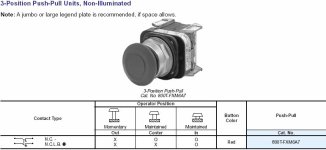
I don't know your process, but a possible 'compromise' might be to use 3-position "Push to Stop/Pull to Start" mushroom-head switches. You still keep the safety of a 'maintained' E-Stop, but provide the ability to start the process from multiple locations without adding an additional 'Start' button at each location. This is from the AB catalog, but other manufacturers make similar switches.
[attachment]
These are simply an Emergency Stop AND Start button combined in one operator. They make illuminated versions as well. I don't know your process, so I don't know how applicable they are for you... :confused:

I personally prefer 'Twist-to-Release' E-stops. Twisting them when they are released does no damage to the switch. Operators yanking on 'Pull-to-Release' E-stops when they are ALREADY released just winds up breaking the switch. Some operators are idiots... :rolleyes:

beerchug

-Eric

3pos.jpg
 
Thanks everyone for the replies. I'm going to lobby very hard that we evaluate every application where and e-stop is needed and make certain that these are brought up to snuff. I will be helped by the fact that the same day I posted this, someone stopped a conveyor using the method that I posted and while she was clearing the jam, the other conveyors pushed boxes onto the conveyor she was on causing a near miss accident.
 
Splitting hairs...

How about this?

We wire E-stops in series, normally closed, etc. When you hit one, it drops out 24 VDC control power, so the machine physically "dies" instantly. It does not, however, kill the PLC. The PLC senses the e-stop and terminates all software control processes, idling all stations on the machine.

My question is about the re-start side. When we reset the e-stop, we turn on control power immediately - no green button. However, the PLC program will not restart any processes until the entire machine has been homed again, which to my mind is a software equivilent to the green button.

I feel like I'm wandering in a gray area here. Our staff electrician says this arrangement is fine, but I wanted to be sure.

Thanks!

TM
 
Timothy,
We do it similar to you. However, we have the separate control start green button to turn power back on. The PLC stays on.

The machine powers up in 'Reset' mode- neither manual or automatic. Nothing can move. The operator must select a mode to continue. For automatic, the machine must be moved to a known state to run. We usually put a button to do this in one shot.
 
NFPA79

Definitely get a copy of NFPA 79 - Electrical Standard for Industrial Machinery. It's easier for the lawyers to help you if you have followed some recognized standard.

Some more sections for reference are:

10.7.4 Emergency Stop Actuators ..."background immediately around buttons...shall be yellow..."

9.2.5.3 Stop - this section defines Emergency Operations (there are acutally different types of emergency stops).

9.2.5.3.3 "....reset of the stop function shall not initiate any hazardous condition..."
 
Tim,

I believe that is how we do it here also, and I think it's the right way. Estops are N.C. in series wired to an E Stop Relay. The relay interrupts power to the output cards and is resettable only by pushbutton on the operator panel. The better designed Estops also have a second seperately wired switch to provide indication of where the E stop was initiated.

R/

Thomas
 
I was also wondering about this recently. I currently redoing a machine and have no idea on the proper e-stop arrangement.

I am planning on having one main power kill button at the main panel. Then having multipule e-stop buttons at different area's on the maching wiring NC in series. The e-stops will kill a main relay cutting all power to the commons on the PLC outputs and also giving the PLC a signal to idle the program. Once a e-stop button is reset an operator would have to set the back to auto mode via the touch panel.

Is this the proper set up?? Would I need to use a machanical green button to restart verses using the touch panel??
 
You should have a separate button to turn on control power. It doesn't have to be mechanical. I have had a touch screen pb that actuated a plc relay output that the control power relay latched around.

The key is that the e-stops must be hard wired.
 
Another possibility -

I'm a little late reading this thread. The current comments are all very good and on-target. For our plant, E-Stop circuits MUST stop motion AND release the energy (electrical as well as fluid) stored in the system.

We do what ChuckM was trying to achieve by using a "ZONE STOP" control. We use this on larger machines with different stations linked by conveyors. We use a maintained YELLOW push-OFF pull-ON operator. The contacts are hard-wired to the enable circuit of the drive(s); another contact notifies the PLC the zone is stopped.

So when the operator needs to stop the line for something, he simply pushes in the switch, stopping the drive; he pulls it out when ready to run again. It is usually mounted next to the E-Stop switch. The production people are very comfortable with it and use it frequently.

~~
 

Similar Topics

Looking for some explanation/history between North American electrical symbols standards (how they relate, what are the latest, what is the...
Replies
3
Views
1,689
Is there anyway to obtain ANSI standards for reading on a college student budget? I was reading the FOMP manual provided by Rockwell and they made...
Replies
4
Views
1,608
Hi, friends! I have some question: i need establish connection between PLC's communications module and electricity meter Elster A1800 ALPHA by...
Replies
0
Views
2,918
Anybody know the ANSI symbol for a Magnetic Reed Switch? I looked in NFPA 79 and it only shows a proximity switch. Are they the same symbol? Thanks
Replies
0
Views
4,414
Back
Top Bottom