Analog Scaling across platforms

TheWaterboy

Lifetime Supporting Member + Moderator
Join Date
May 2006
Location
-27.9679796,153.419016
Posts
1,922
This may be a dumb question for some but I gotta ask anyway.

Can someone give me the 50 cent tour of the reasoning behind all the different data formats and scaling needed when working with Analog modules in SLC and Micrologix?

I was used to PLC5 which was pretty simple and now mostly Contrologix which is really REALLY simple to implement. Scale an input from 0-100 and output to 4-20mA and they just work.

Lately I have been working with SLC 5/04, SLC 5/05 and some Micrologix 1200's and the analog Scaling required in these is truly bizarre when compared to the others I mentioned.
Using input scaling of 0 and 100 and a output scaling of 3687 and 16367 to get an output of 4-20mA is not intuitive in any way.

Will someone help me understand why this is necessary and if there is a way to understand the differences in a more intuitive way? Is it historical? or legacy?
 
in the old machines this conversion was done for you internally, now you can get to the registers direct, or use a simple subroutine to do so for you.
 
In the PLC5 (Older) this was done in the module config or you could get to the registers directly if you were so inclined, In Controllogix (Newer) this is again done in the module. But in between, (SLC, Micrologix) the modules didn't have the same style of configuration making the manual calculations necessary. And the resolutions are odd,i.e. 12.3 bits of resolution in the SLC 5/04. 12.3 ???
 
Your question certainly doesn't make sense to me. The PLC5 analog I/O modules were far more complicated to work with than are the more recent modules, IMHO. Have you never actually configured a PLC5 system from the ground up? Try setting up a 1771-IFE module for a mix of voltage and current inputs and then get back to me.

As to your confusion regarding scaling with the SLC modules, it sounds as though you're working with some of the modules that offer no software based configuration options. All analog I/O modules operate within a numerical range that is determined by the resolution of the analog to digital converters chosen to build that particular module. This is true whether your particular PLC's configuration software allows you to see the base resolution of the module, or not.

For instance, a 1746-NI4 analog input module, when used as a -10 to +10 VDC input module, offers 16 bit resolution and returns numerical data to the processor in the range of -32,768 to +32,767. However, when this same module is reading a 0 to +10 VDC signal, you will have access to only 15 bits of data and the processor will see numbers returned in the range of 0 to 32767. If your input range is 0 to 5 VDC, then you sacrifice yet another bit of resolution and the module will return numbers in the range of 0 to 16384. When reading an instrument with a range of 1 to 5 VDC, you are tossing out any data below the 1 VDC zero offset and your effective resolution is then limited to 3277 to 16384, or 13.67 bits. This is the same resolution that you would see from this module with the far more typical 4 to 20 mA input range. While this module features a 16 bit resolution A/D converter, that resolution is only available when reading the full -10 to +10 VDC range. In addition, this module offers no software configurable scaling parameters. You only have access to DIP switches to choose voltage or current inputs. It is then left up to the programmer to perform any required scaling of the numerical data that the module returns to the processor.
 
Try setting up a 1771-IFE module for a mix of voltage and current inputs and then get back to me.

By way of information for readers who may encounter this thread now or in the future, configuring 1771 analog cards used to be quite a bit harder than it is now with the old AB or ICOM software. But in RSLogix5 its not difficult and takes less than two minutes.

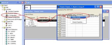
Open IO configuration in the project tree, Right click chassis and pick display chassis. Click the slot and insert a module from the list. Then right click the module and pick display module.

attachment.php


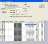
You'll be prompted for the addresses of the N files to use for block transfers, or you can let RSLogix pick the addresses for you. Next you'll get a configuration window. Here you configure the channel ranges, data type, etc. (Note that for some modules, such as the 1771IFE, you still have to set onboard jumpers to select voltage or current). If you are using smarter modules such as the N series analog modules you'll see options to scale the engineering units, making the setup nearly as easy as a ControlLogix module. Also here you add symbols and descriptions to associate with the address for the input. I strongly recommend you take a minute and do that, then you can program by symbol name instead of address, making the programming task even easier for yourself.


attachment.php


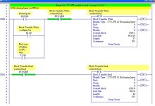
After you are done you can have RSLoigx go ahead and automatically insert the Block transfer read and write rungs into your program, already configured for you. If you are using an enhanced processor it will use a BT file. If you are using a standard processor it will setup an N file for you.

attachment.php


TC05021301.jpg TC05021302.jpg TC05021303.JPG
 
Last edited:
Agreed, the jumpers can be a PITA. Having set up many systems with the old ICOM software I really appreciate the tools in RSLoigx5, however I haven't done a ground up PLC/5 system since the mid-late 90's. There are probably relatively few programmers who have since the turn of the century. I have expanded several existing systems and the Logix5 tools have come in handy. That said, the PLC/5 is still one of my favorite platforms to work with, despite its age.
 
Thanks for the feedback guys, While I never had any problem configuring and using the PLC-5 line (using N or BT registers, a,b, and C revision modules with the different data size requirement and of course those goofy jumpers) When I started this job I found many BTR/BTW with N registers were configured differently and behaved strangely. The programmer took into account only the channels that were in used. i.e. instead of 37 or 39 words available to the BTR/BTW, there might be only 8. This appeared to work because the channel data was still there and that was the only concern. Stacking these N registers too close led to interesting behavior since the module expected a fixed number of 37 or 39 depending on revision. But I digress...

The area of information I see I am weak on is the -10 to +10v being the standard criteria, or at least the point at which the designers chose to make the entire resolution of the A/D available.

In my isolation all I ever use is 4-20ma loops so I never paid attention to the other ranges. I just assumed that everything should have X number of bits available and be configurable somehow to apply those bits to whatever range of input signal was desired.

For example, with the PLC5 I thought I had 4096 (12 bits) of resolution regardless of which signal I was reading. 0-5 or 4-20. Silly me I assumed that would be true everywhere. When we went from PLC5 to CLX and those modules scale very nicely reinforcing my assumptions. Then came the SLC work... thats when this started to get wierd.

So while you said my question didn't make any sense, your answer was spot on and makes sense from the perspective you presented. I never thought about it like that. I might be back with another question when I look at these this week.
Thanks for taking the time.
 
SLC and uLogix have a huge range of actual A/D conversions available in the analog IO modules for those controllers, ranging from 8 bit to 16 bit. You have to RTFM for the AI or AO module that is being used. Virtually every AB analog IO module for the SLC and uLogix families is well documented as to the resolution, and as important, where that resolution falls in a 16 bit integer word. Because of the history for this family, you can run across all kinds of AD/DA conversion. However, I have always found that the module instruction manual documents very well the characteristics of the module and how the data is mapped to or from SLC or uLogix memory.

OK, so once you've read the manual, you see what the resolution of the module is. Map your actual hardware signal into that and find out what bits are of use to you. Now check to see where those bits are going to be mapped into a 16 bit integer word. Often, you find that a 12 bit resolution is being mapped to bits 3-14 of the word. Why is that?

Well, my guess is that really gets back to the history of the SLC. The SLC in particular is still set up for PID loops that output over a range of 0 - 16383. They can be set to run differently these days, but back in the day the PID block was set up for that output range. That in turn would often map directly to an analog output which is of course why they did it. On the input side, the use of bits 3-14 for a 12bit AI gives you the same scaling on the input without any further fuss.

Aside from that, IDK either LOL. You definitely need to watch scaling on SLC and uLogix IO, but it's not that big a deal - especially since the advent of SCL and SCP blocks. One of my pet peeves (and one of my ways to evaluate skill set) is the ability of a PLC programmer to handle analog IO and scaling. The number of people who are programming but who don't seem to understand the equation of a straight line, or scaling, or binary arithmetic seems to be very large!

Resolution is resolution, however you eventually slice it. And, although I usually convert to EU on input, run my logic on EU and then convert back to raw on output, that costs time and memory. Back in the day, all of that was bypassed and AB attempted to set up the word values so that you could read in, run the logic and PID and then write out all in raw. That, I suspect, is what leads to the "weirdness" you see in the SLC and uLogix AI/AO.
 
Maybe I'm just "old school", but I prefer to work with raw numbers in my PLC programs. It's not as big an issue (so far as lost granularity) now that almost all PLCs support floating point data, but I still do it, unless my client specifies otherwise. I'm of the opinion that scaling values within the PID control block simply adds unnecessary complication.

With that being said, I do often re-scale analog inputs and/or outputs outside of a PID block in order to change the range represented by the raw numbers within the PID block. For instance, I might scale a PV from a 1746-NT4 thermocouple input module in the range of 0 to 2500.0 degrees (0-25000) such that the 0-16383 PV range in the PID block represents 0 to 800 degrees for a process that typically operates in the range of 400 to 600 degrees.

In such a case, using the full scale of a type K thermocouple input significantly reduces the useful resolution of the PV, since the normal operating range of the process occupies such a diminutive slice of the instrument's full scale of measurement.

I would likewise rescale the PID's full resolution CV of 0-16383 to 6242-31208 prior to sending the PID CV to an AB 1746-NO4I 4 to 20 mA analog output module. As for displaying all of this data to the operator in engineering units, it's my preference to perform that function within the HMI, and to also scale the Setpoint entry within the HMI so that the PID block receives a Setpoint value in the range of 0-16383.
 

Similar Topics

Hello, We monitor the temperature of a pipe via a 4-20mA temperature transducer. This goes into DB135(Read Analog Inputs). The issue I have is the...
Replies
0
Views
621
Hi all! I have a question about RSLOGIX and Analog input/output scaling So we have an existing controller with an IF8I and OF81 card. My...
Replies
3
Views
929
I’m trying to perfect the HMI interface for analog configuration. I’ve provided the user the same options for all analog inputs, as follows...
Replies
10
Views
1,664
Hi I have a modicon 984 with proworx 32 that is scaling an analog input, and I need to adjust the scaling. I have new analog input values and %...
Replies
3
Views
1,719
Hi, i've write this AOI to send a ControlValue comes from pid and control a valve. this valve is controlled through analog output. the rang of...
Replies
0
Views
1,020
Back
Top Bottom