Can I have some help?

josesaucedo

Member
Join Date
Nov 2005
Location
Van Nuys, CA.
Posts
78
Hello guys,

I'm here again experiencing a new problem. Before I continue I want to thank everybody in this forum who take the time to help people like me that start getting in the world of PLC... Thank you again.

Few days ago we had a power outage in our facility, I have a machine that after this power outage did not want to work anymore. I did troubleshoot any possible mechanical and electrical problem, some times a mechanical problem causing a sensor not reading like an air cylinder not retracting or just something not making back to home position and stopping the machine from starting its cycle. I did find all the I/O's OK, so I decided to connect my lop top to the PLC, and again, all I/O's were OK.

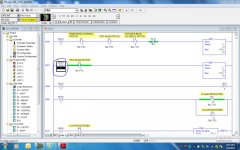
I have attached a copy of the program just in case any one can open it and check this. I have a two hand switch to start the machine after the "material present photoeye" and the "material switches" are made. When I depress the two hand switches the machine should start the cycle, and it does it. But, if I toggle bit B10:0 5 any where in the program, the machine starts the cycle. Can any body give a little help?

Thanks.
4133 snipping.jpg
 

Attachments

  • 4133_BAK004.zip
    21.6 KB · Views: 27
Last edited:
In the snipping you posted you circled B10:0/5 on rung 7. It seems B10:0/5 turns on when there is a 5 in N7:0. Rung 6 is where 5 is moved into N7:0. Are all the conditions on that rung satisfied when you attempt to start the machine?

I see B10:0/2 as a condition there. That turns on when there is a 0 in N7:0. The rung that needs to be satisfied for that is Rung 0 in Lad 2.

Hope this helps.

Dave
 
Dave, what do you mean when you say if the rung is satisfied? Do you mean the rung being like energized? At what moment the move instruction in rung 0 will be on?, when there are some inputs that have to be on when the e-stop is in its closed position and others will be off (sensor reading retracted position and others not reading because of the condition). Also there is one open and one close e-stop instruction in series that change in opposite depending the condition of the e-stop.
 
Hi,

By satisfied I mean in order for rung 0 on Lad 2 to move a 0 into N7:0 each condition in the rung has to be true. If you are monitoring online you should be able to see each condition in that rung as being on or off. If all conditions are on (turn green) then a 0 will be moved to N7:0.

Honestly I was just looking at that rung (rung 0 LAD2) and the very first two conditions in that rung would (I think) not allow that rung to ever go true. I think it is looking for the same E-stop (I:0/0) to be both on and off with the first two conditions. I dont work with AB as much as a lot of people here and maybye I am missing something. I hope someone will see this and help me out here as this isnt really making sense to me.

I hope I have been helpful,

Dave
 
Thank you Dave,

And yes, you have been very helpful to me, I just want to understand well what you are saying. Should all the instruction in that rung (0) be true at the same time?, because I:0/1, I:0/2 are not always true when there is material in the machine, depending the shape of the material is the sensors (inputs)that will be on, while I:0/3 and 4 are true every time there is material in the machine. That's why I don't understand if they have to be true at the same time or as long as they are true at some time.

Thank you.
 
I think it is looking for the same E-stop (I:0/0) to be both on and off with the first two conditions. I dont work with AB as much as a lot of people here and maybye I am missing something. I hope someone will see this and help me out here as this isnt really making sense to me.
Dave, as you said, the E-Stop can be on or off, but not both at the same time. If someone would print program to a PDF file and attach that, then I could see the Rung 0 situation. I don't have the newer RSLogix to open it myself.
 
Since I:0/0 can't be true AND false on the same scan, that XIO I:0/0 XIC I:0/0 in series looks to me like that rung was disabled on purpose.

🍻

-Eric
 
I think you have errors in the I:1/0 E-Stop instructions on both Rungs 0000 and 0001. Because the E-Stop is either ON or OFF, it can't be both, therefore neither of these 2 rungs (as written) can ever move a 0 to N7:0.

What could the error be?

Some possibilities:

1. It could be that the XIO's for I:0.0 for both rungs were put in as a test for Slot 0 Inputs and Outputs, and then not removed, or purposely disabled until again needed for the test.

2. There could be only one E-Stop, and the XIO I:0/0 instruction on both rungs should not be there and should never have been there.

3. There are really 2 physical E-Stop pushbuttons, and the address for one is I:0/0. The other? I can't tell. It could be I:1/0, or I:0/7, or I:0/9. Who knows?

Either case, I think there is at least one error on both rungs. There could be other errors. Do you really have 24 inputs in your Slot 0?
 
Last edited:
Thanks Eric,
Can I removed the first instruction I:0/0 XIO? Some thing is not right because no body has access to this PLC program, in fact, this is the first time I connect to it. It's been like that for many years, or unless something changed after the power drop I had. Could that be possible?

Thanks.
 
Looks like I have to check the wiring because on a picture I took before disconnecting the wires to change the plc, it shows wires connected to inputs 7 and 8, all labeled, but I don't find them in the program.

Thanks guys.
 
Here is the rest of the file.
That reinforces my thought about rungs 0 and 1 being disabled. Someone disabled those rungs and simply forced a zero into N7:0 when the E-Stop is pressed, regardless of other conditions. I wouldn't have expected it to be at the end of the program, but rung order may not be overly important in this application.

I haven't looked at the whole program yet, but based on what I have seen, you should be able to simply ignore the first 2 rungs, since they appear to be disabled.

🍻

-Eric
 

Similar Topics

Hi all, hope you are having a great day, I am in need of your help to create a AOI or program that does this kind of job: I have a IO Link...
Replies
0
Views
46
please help me . I have to make this ladder diagram and I can’t figure it out :(
Replies
12
Views
305
Hi Everyone, i was hoping for a little help with this module. i have data that needs to be read from a different plc through the Modbus plus...
Replies
11
Views
203
Hello, I am trying to replicate a piece of logic on the PLC5 onto an SEL RTAC. I am using ladder on SEL and FBD. I am having issue on the ladder...
Replies
13
Views
219
Back
Top Bottom