Safety PLC and PNOZ in S7 F CPU

userxyz

Member
Join Date
May 2002
Location
any
Posts
2,768
Hi,

It's the first time that I have to build logic from scratch in safety Functions.
When you have a standaard PNOZ, you have 2 channel-inputs.
The question my boss asked was if a 1-channel Emergency-Stop circuit can be combined with a 2-channel Emergency-Stop circuit in the Safety logic of a PLC.
I don't know much about safety, but isn't this just the same as other logic ?, except that it Runs in a Fail-Safe area, an area that keeps running when the cpu stops because of hardware or software faults...
My boss thinks that an emergencystop input has to be 2-channel or single-channeled, combinning not possible ?

Someone who can tell me the comparision with a Multipnoz ?

Thanks,
Regards,
Combo
 
You will need to post a diagram showing how you intend to combine a single channel e-stop with a dual channel e-stop

If an S7 F-CPU stops then all program execution stops and the F outputs go to their fail safe state. The safety program is called (normally) from OB35 like any other block call.
 
You will need to post a diagram showing how you intend to combine a single channel e-stop with a dual channel e-stop

If an S7 F-CPU stops then all program execution stops and the F outputs go to their fail safe state. The safety program is called (normally) from OB35 like any other block call.
I agree.
But.. I think you can use a "single-channel" as well it doesn't have to be "dual channel" for that particular channel.
It can be defined as a single.
But.. you will have to use a permanent jumper for the "second channel".
The "Re-Integration" also has to be set up as well.
Hope someone will jump in and correct me if I'm wrong.
 
Hi

I don't know of any Safety sil level or performance level that allows a mixture of single and dual channel e-stops. Just be careful and I would ask for the risk assessement and this will answer what level it should be.

Donnchadh
 
Hi

I don't know of any Safety sil level or performance level that allows a mixture of single and dual channel e-stops. Just be careful and I would ask for the risk assessement and this will answer what level it should be.

Donnchadh

^^^ This. The SIL level determination for the area in question should answer this question.

I could also ask if you are thinking of combining an F CPU with a PNOZ module? If so, why? And don't forget to use the TUV safety blocks for the safety function, not just the standard LAD/STL!
 
more complex

hi,

the safety looks complexer then I tought it would be. yes indeed its a combination of pnoz and failsafe plc. The pnoz are used for reading emergency stops and doorcontacts. But we als have additional emergency stops on an et200s (new installation). Each freauency drive has 2 safe inputs. The first is a quickstop and the second a safe torque off. After someone hits a emergency stop, the drives must do a quickstop and after a few seconds the safe torque off must be high. But timers arent allowed in safety, how can we do this then ? We will connect safe outputs to the safe inputs of the danfoss drives.

Tnx for your help.

Kind regards,
Gerry
 
The Siemens F_ESTOP1 block that comes in the distributed safety library has two outputs. One switches off instantly and the other after an adjustable time delay.
There are also timers included in the safety library.

Hope that helps,
Phill
 
Hello

Hello,

Thanks, that's what I need.
An additional question...
What to connect on E_STOP of that function...

I mean, When you do this with a hardware modul instead of the Safety PLC, then you connect 2 safety-circuits (channels).

On the E_STOP, I can connect a FS input. But, that's only one channel ?


Thanks for your help,

Kind regards,
Combo


The Siemens F_ESTOP1 block that comes in the distributed safety library has two outputs. One switches off instantly and the other after an adjustable time delay.
There are also timers included in the safety library.

Hope that helps,
Phill
 
F_1oo2DI

Hi,

There is als a F_1oo2DI FB in the Safety Library.
So, for a double Emergency-Stop I must use this Fb I think ?
But, after this Emergency Stop I need the F_ESTOP1 FB for these 2 evaluated Inputs. May I use a TempVar on the Q of the FB F_1oo2DI and then link the tempvar to the Emergcy input of the F_ESTOP1 FB ?


Thanks,
Combo


Hello,

Thanks, that's what I need.
An additional question...
What to connect on E_STOP of that function...

I mean, When you do this with a hardware modul instead of the Safety PLC, then you connect 2 safety-circuits (channels).

On the E_STOP, I can connect a FS input. But, that's only one channel ?


Thanks for your help,

Kind regards,
Combo
 
Example

Hellon

I tried it but I get the messages that I350.5 and I350.4 does not match the channel structure of the F-IO's ???

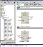
Look how I programmed 2 DI's with descripantiontime 200ms and a FB that manages the safe off and safe off delayed.

ES.jpg

Thanks,
Combo

Hi,

There is als a F_1oo2DI FB in the Safety Library.
So, for a double Emergency-Stop I must use this Fb I think ?
But, after this Emergency Stop I need the F_ESTOP1 FB for these 2 evaluated Inputs. May I use a TempVar on the Q of the FB F_1oo2DI and then link the tempvar to the Emergcy input of the F_ESTOP1 FB ?


Thanks,
Combo
 
If you defined your input as a 1oo2 in the hardware config, then you use it as one input in your programme.
All the configuration of 1oo1 / 1oo2 and discrepencytime is done in the hardware config
 
Ok

Ok.

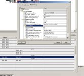
This is my Hardware Config.
ddd.jpg

The Channels 0 and 4 with Adress offset 350 means that my 2-channel Emergency Stop will be connected on Input I350.0 and Input I350.4.

So I only need the F-ESTOP1 if understand you well. But what input should I use then ? One of both or an interfaced one via a Safety DB ? How does that work ?

Thanks,
Combo

If you defined your input as a 1oo2 in the hardware config, then you use it as one input in your programme.
All the configuration of 1oo1 / 1oo2 and discrepencytime is done in the hardware config
 
Your 2-channel E-stop will have input no. I350.0, I350.4 is not used,
The 2 channels are connected in the Hardware Config.
If you had made your config as 1oo1, you will have 2 inputs I350.0 + I350.4
 
k

Hi,

Thanks.
But what is the FB 1oo2 for then ? WHen you must do it in the HWconfig, the FB 1oo2 makes no sense anymore, or is it to combine 2 completely different Inputs in a 2-Channel functionallity ?

Kind regards,
Combo


Your 2-channel E-stop will have input no. I350.0, I350.4 is not used,
The 2 channels are connected in the Hardware Config.
If you had made your config as 1oo1, you will have 2 inputs I350.0 + I350.4
 

Similar Topics

I've ready through the the previous posts, and we've worked with safety design for a long time. In the past, we worked with Pilz directly, and...
Replies
9
Views
563
Hello, I have been programming with Logix for over 2 years now, my current job just put me on a job where we had to change some of our original...
Replies
7
Views
940
So I'm still a little new to LC muting, and currently do not have a test bench. THE SITUATION My LC function is set to manual reset. I mute the...
Replies
3
Views
945
Hi guys, This my first time posting hope I get help in my issue.. I have Allen bradley control logix safety PLC (1756-L61S) connected with...
Replies
11
Views
2,303
Good evening, I'm primarily a Siemens user, but I have an incoming project where I need to use Allen Bradley everything. So far I know that the...
Replies
7
Views
2,639
Back
Top Bottom