Siemens 331 AI Module Signal Fault

Tim James

Member
Join Date
Mar 2012
Location
Texas
Posts
92
Let me start by saying I am relatively new to Siemens controllers. I have a 314 CPU with a 331-7KF02-0AB0 AI module attached. The module is setup for 2 wire transmitters (in the hardware configuration and the jumpers). My analog values read just fine, but I have an SF red status LED on the module. Going into step 7, I can see that there is a channel fault error and when I look at the specific diagnostics I can see that all channels 0-7 are showing a wire break fault.

Seems straightforward enough, but I do not have the wire break detection enabled on any of the channel groups. I have disabled 'check for wire break' diagnostic interrupt' and 'hardware interrupt' on the module and I still get a wire break fault on all channels. 4 of the 8 channels are spares so I completely 'deactivated' them in the hardware configuration and I still get a wire break fault even on these deactivated channels.

I have jumped across all unused channels to M_ana and it had no effect. I do not remember seeing this issue on the last 6 control panel setups I have programmed (which all used the same hardware).

Any advice on things to check in the hardware configuration, or another way to disable the wire break faults would be appreciated. Like I said, the analog signals are being read fine, but no one wants a big red fault like on even if everything is working ok. Thanks in advance.

Tim
 
To further complicate matters, I began programming a second control panel (same hardware configuration as above) and I can't get the dang AI module to 'START'. Program and hardware configuration is downloaded, controller is running, discrete in and discrete out modules work fine, but my raw inputs from the AI module are stuck at zero. All statuses are green across the board.

I've had this happen before and it seems like I clumsily poked around at the controller setup until somehow it magically started working. As much poking as I have done (reprogramming, cycling power, changing AI module settings, reprogramming in STOP mode vs RUN) I can't get the AI module to read any values.

There are two things that I feel like are related to this issue that I can't figure out:
1) I keep getting a warning during downloading about something being in 'test/commissioning' mode and that it may affect the download. I can't find any settings anywhere regarding test/commissioning
2)The module is giving me a diagnostic warning that 'parameters have not be assigned' or 'parameters have not be written'. I completely don't understand this because I established all the AI module parameters and when I first downloaded the program to controller I wrote the software and hardware configuration. Now 'download hardware configuration' is always grayed out. Even when I make parameter changes to the module it is still grayed out.

Clearly something is happening here where I am not setting the configuration for the module and/or I am not properly starting the module and putting it 'RUN' mode (yes the CPU is in RUN). I've perused the Siemens documentation, but it is poorly written and the programming 'how-to' is in some ancient version of step 7.

Any thoughts or tips would be appreciated. I feel like this may be the reason I can't clear the SF fault I mentioned first as well, because I'm never actually writing/saving the hardware configuration/parameters to disable 'check for wire breaks'.
 
Regarding the analog-
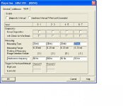
Configured like the screen shot?
Ive only seen these settings or no 24vdc cause a SF on the analog module
You are reading PIW values in a VAT table?

ana.jpg
 
Last edited:
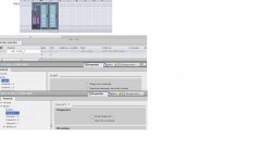
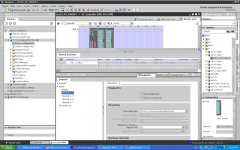
More or less, yes, that is my configuration. I am using TIA Portal though, not Step 7 directly.

Wire break is disabled, hardware interrupt is disabled, diagnostic interrupt is disabled. 50hz filter is enabled, all channels are set to 4-20mA two wire, except the unused channels which are 'deactivated'. How I get wire break faults on deactivated channels escapes me, and moreover makes me think that my parameters are not getting written to the module by the CPU.

While I feel like the problems may be related, at the moment I have one module working perfectly with a SF light, and one module with no SF light that has all the raw inputs stuck at 0. Same program, same HW configuration, same wiring.
 
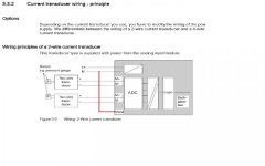
Interesting- so all of the analog config reading values in the watch table..right? And measuring block set to D ?
Remember- Im just trying to help

ana1.jpg
 
No worries, I'll take any advice I can get.

Jumper blocks are all set to D. I'm actually headed back to the office to do some more tinkering with the system and I can check the parameter values in the watch table once I'm back online with the controller.
 
-24 VDC common is floating at the moment. It is not tied to ground. I just have a 24VDC power supply on the panel for testing, the panel would normally receive a 24VDC source in the field from another location.

On another note, regarding the module that has raw values stuck at zero. I just pulled up in the watch table the raw values direct from the module %IW288:p and they should appropriate raw values. The tag in the CPU %IW288 shows 0. I checked the process image of the CPU and it is extended to 350 so 288 should be within the process image. So the raw input is there, but it's not making it into my CPU tag somehow.

Sorry to have two issues going simultaneously here.
 
I at least got one issue resolved. The module that was not reading values, or rather that wasn't pushing the signal values through to the CPU process image is now doing so. I was planning on just rebuilding the hardware profile from scratch to see if that would do anything, but what I did instead was go offline with the controller, close TIA Portal, open my project back up, go through all the hardware configuration parameters (none of which I changed since I had already set them) and then downloaded 'ALL' to device (the device being the CPU). Since I just reopened portal, I was able to select download all which included the hardware profile and for whatever reason on this go around, the analog module started passing values through to the PLC process image tags. I also checked the module diagnostics after doing this and the 'module parameters have not been set' message was cleared. Someone once told me to download everything two or three times when it comes to Siemens controllers, I guess they were onto something.

Regarding the SF fault, since I now have one module working properly with no SF light, and one working properly with an SF light (wiring is identical), I can only assume it's an issue with the module parameters. I'm going to go back in and do the same thing on the setup with the SF light on (open the project, double check the module parameters offline, and do a 'download all') and see if that doesn't set in the module parameters and clear out the wire break faults.
 
Last edited:
Getting TIA Portal to transfer Hardware settings does seem 'odd'. You have to go offline, right click on the PLC and select Download to device / Hardware configuration, then TIA goes back online and transfers the configuration. Sometimes even that doesn't work, I changed a PID loop to Reverse acting and TIA still told me that no changes had been made, so it refused to download the configuration. It needs a big red flashing button that tells TIA to do what I want, not what it wants. I keep an SD card handy for when TIA plays up, put the program on that, shove it in the controller, and you can bypass TIA (soon to be renamed PIA, Pain - In the - ???).
 
TIA (soon to be renamed PIA, Pain - In the - ???).

An excellent summary of my sentiments. I was able to clear the SF light on the module using the same tactic as before. Opened the project fresh, put the CPU in stop, without attempting to go online just selected download hardware configuration, and after that completed the faults cleared. It seems like an obvious solution in retrospect, but I still don't understand why TIA requires such a convoluted process just to set some hardware parameters. Other platforms may ask me a half a dozen times if Im sure I want to do something before it does it, but at least they let me do it without jumping through a nightmare of cryptic logistical hoops.

Hopefully this helps someone else out there. I appreciate everyone's help on this.

Tim
 

Similar Topics

Hello Experts, I am going to be integrating an AI module into an existing panel and wants to know what should be measuring range setting when i...
Replies
0
Views
1,874
Hello, We have a project in which we will use the 6ES7331-7PF11-0AB0 TC module for measuring temperature. We use K type thermocouples normally...
Replies
1
Views
5,454
Hi all, i have a problem with the above card, my rack has two of them and the same issues! In Channel 0 and 1 on both cards i have 2 wire...
Replies
7
Views
1,861
I've been fighting a problem with this 8 channel analog input card mentioned in the title. I believe it's something I'm doing in the wiring but...
Replies
3
Views
1,707
Hello Experts, I need your help about this issue of mine about my Siemens Analog Input Card SM331 having SF LED lit. I know this is system fault...
Replies
2
Views
4,480
Back
Top Bottom