AB 5/04 binary 8pt output card to pre-programmed alpha-numeric display

TheCaptain2000

Lifetime Supporting Member
Join Date
May 2004
Location
Georgia
Posts
51
In changing from an S5 to an Allen Bradley 5/04, I need to figure out how to convert an integer to an 8-bit or 16-bit binary format. I need to be able to output this binary code on a 8pt or 16pt output card to be read by a pre-existing pre-programmed alpha-numeric display built by the OEM of the machine.

For example, if there is nothing to display on the OEM display, the integer 0 is in play thus showing 0000 0000 on the AB output card.

Next, if the E-Stop is engaged, the integer 1 is in play, thus showing 0000 0001 on the AB output card. The display then shows the "Emergency Stop Engaged".

When the integer 2 is in play...0000 0010 is on the output...another message is displayed...and so on.

I know I can make an HMI do all this work all day long, but this has become a personal learning mission of mine along with trying to keep the operators workstation the same as before keeping the users learning curve to a minimum.

I have seen examples in the forum before where I could just MOV or COP the integer directly to the output card, but it does not work for me.

Also, I am currently using a counter/timer combination to cycle the messages in the common event there are multiple messages to display. How can I program to show only the messages that are needed versus just skipping the unneeded pre-programmed messages and cycling through the 30 or so messages by either showing or hiding each individual messages? I would imagine not using a counter for this, but perhaps a FLL (Fill) instead...thoughts?
 
absolutely...pattern is standard binary...

0000 0001 is 1
0000 0010 is 2
0000 0011 is 3
0000 0100 is 4
0000 0101 is 5
...
0000 1111 is 16
0001 0000 is 17
...
1111 1111 is 256
 
That's the way an SLC encodes integer values, so MOV or COP ought to work fine.

Can you explain exactly what 'does not work' about that ? Are you getting unexpected bits on in the output word ?
 
I'd like to know that also, you should be able to use whatever error routine to set bits in an integer file, then move the integer to your outputs since they are both the same size. If nothing else you could use a seperate XIC to each output bit but that should not be necessary
 
Using the MOV command...I set the source as an constant integer and the destination as O:16 (8pt DC Source Output Card)...Error comes back as "address must be specified to word level"

Using the COP command...it does not let the source be a constant...but when I make it an N address that I read from...then it verifies the individual rung...but not the project...sites a compile error.

Using RSLogix 500 version 6.3...SLC 5/04 CPU 1747-L542 Ser B rev 3...with OS401 Ser B Frn 7
 
Tell us the complete catalog number of your output card and the slot its in.

An output word address would look something like this O:1.0 if the card was in slot one (1).

I set the source as an constant integer

A value or an integer address like N7:0?
 
Last edited:
SLC-500 I/O data tables are addressed "O:s.w/b"

I or O indicates Input or Output.
s is the Slot number.
w is the Word number. 8 or 16 bit I/O modules only have Word 0.
b is the Bit number.

As has been mentioned, you need to address Word 0 of the correct Slot.

In the SLC-5/0x controllers, the first slot to the right of the CPU is Slot 1. The largest single chassis is 13 slots, so that's Slots 0 through 12.

You can only have 'Slot 16' if you have more than one chassis with an interconnect cable. Just start at the CPU, and count upwards, left to right.
 
absolutely...pattern is standard binary...

0000 0001 is 1
0000 0010 is 2
0000 0011 is 3
0000 0100 is 4
0000 0101 is 5
...
0000 1111 is 15
0001 0000 is 16
...
1111 1111 is 255

Just had to be done... :)

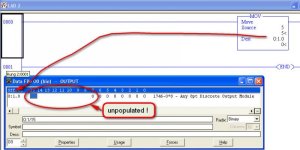
Just be careful with that MOV.... I'm not certain if the processor treats the destination O:x.0 as a BYTE value for an 8-bit module. Something you will have to test. It certainly doesn't {appear to} populate the Output Image table for the upper 8 bits. See the pic attached

If it does treat the destination as a BYTE value, then any value above 127 you MOV into it will cause the Overflow status flag to be set {and consequently the Overflow Trap flag S:5/0 will also be set}.

Then, if the overflow trap bit is still set at the end of the logic scan, the processor will Major Fault.

2013-07-10_203746.jpg
 
Last edited:
IF

You use an 8-bit Output module

AND

You must use values 128 to 255

THEN

You can avoid the (possible) overflow by having eight bit-moves from your source intefer to the output module channels....

2013-07-10_204158.jpg
 
Sorry to get back to everybody so late...

Yes, I did realize my mistake on the binary code illustration...my apologies.

However, the O:16.0...that was all. Never done this type of program before, but always have fun learning!!!

I even figured out how to get the sequencer to work to scroll though the errors properly!

Thank you everybody!!!
 

Similar Topics

Hi folks, I'm trying to parse a binary string on a Red Lion DA30D using a Raw UDP/IP input port. I've done this before with ASCII strings so I do...
Replies
38
Views
961
So here's my situation, I have been tasked with modifying the logic to mimic a button press in the PLC. I have two identical machines however one...
Replies
6
Views
534
Hi, I want to extract every second bit of a double word and place it in a new word but the position of placement should be from 0,1,2......15...
Replies
17
Views
3,050
Hello, I am trying to convert a incoming string that is in Binary format (See attachment) to a DINT. Any ideas? When I use the STOD command it...
Replies
6
Views
2,191
How can I read individual binary bits from a SLC500 within FTH SE? With the Tag Browser I can get to the Binary Files and get each Integer from...
Replies
5
Views
1,587
Back
Top Bottom