MLX 1200 - channel 0 wiring?

hepworth07

Member
Join Date
Jun 2013
Location
Blackpool
Posts
7
Hello all,

I have a micrologix 1200 series C PLC (L24 - BXB) I have created a program that outputs an ASCII string via channel 0.

I am sending (123 is an example, the number varies in the program) 123<CR> at 19200 baud, 8n1 using RS232, 31 32 33 0d in Hex.
I can get this data to appear in both real term and hercules, when I connect the PLC to my PC in run mode.

however, I cannot get it (or anything) to appear on my serial slave display. London Electronics INT2-S2-0-0-0-RDLV-DC-0 http://www.london-el...s/INT2S_F21.pdf
I have sent the display back to the manufacturer, who have confirmed it is working and are going to send it back shortly.

The manufacturer has told me the settings for the display based on my ASCII string and com port settings.

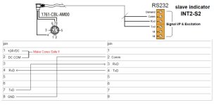
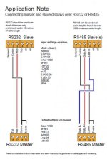
The only thing I can think of is the wiring connection. It is currently wired as shown in the attached image titled capture.jpg (RS232)

I am using a 1761-CBL-AM00 cable, with one end cut off to connect the cut cables to the screw terminals on the display. based on the 8 pin mini din pinout from this picture
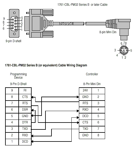
1761-cbl-pm02.gif


Is that drawing accurate? or is it something like I have to connect the RTS to the CTS etc...

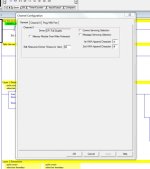
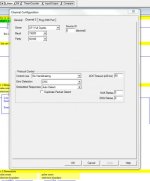
Channel 0 port settings attached below. The instruction I am using is an AWA, again I have got the ASCII string to display in real term and hercules. The program file is attached below, if it helps.

Any help would be brilliant before I pull all of my hair out

Thanks

James
Capture.jpg Channel 0 general tab.jpg Channel 0 channel 0 tab.jpg
 

Attachments

  • UNTITLED_BAK008.zip
    18.8 KB · Views: 39
I did mess about with the ASCII setting for a while, but its currently set to DF1 full duplex because I read somewhere (possibly a manual) that it had to be in that mode for the AWA and AWT instructions to work.

I can get the MLX to send the ASCII string in DF1 full duplex, would it not be exactly the same string being sent in both DF1 and ASCII mode?

I'll try setting it in ASCII and check with realterm/hercules.

I won't be able to check it with the display for maybe a couple of days, waiting for it to be posted back to me.
 
I've set it to ASCII and I get the same readings with realterm/hercules, which is what i want.

I think the problem is with the wiring, when it's connected to the display. because the display acted like it wasn't receiving anything.
 
That wiring diagram for your device seems a little odd to me. Why wouldn't you connect the transmit line (of the PLC) to the receive line of the device and the receive line(of the PLC) to the transmit line of the device? Common to common.

Glancing over the manual that wiring diagram you posted is for connecting two displays together in a master/slave configuration.
I would wire it as suggested above.

How do you have it wired? Drawing if you can or pin numbers to pin numbers.
 
Last edited:
I noticed the same. That diagram is display-to-display.

I assume you have belled out the coloured cores in the 1761-CBL-AM00 cable that you cut?
You need the cores from pin 4(RxD), 7(TxD) and 8(GND).

The attached diagram is how I would wire it up, same as Mickey has sugested.

Just be careful while using the AM00 cable. When connected to the Micrologix, the cores from pins 1 and 2 will have 24VDC across them. These are normally used for powering devices such as the 1761-NET-AIC.

Also note, Channel 0 on the ML1200 is a non-isolated port. Normally it would be good practice to use an AIC as an RS232 isolater between the PLC and any devices. Your call.

G.

hepworth07_cable.jpg
 
If you plan to just chop the end off an AM00 cable, a less expensive ($30) alternative is the EA-MLOGIX cable from AD. The pinout of this cable can be found on page 6-22 (PDF page 22) of THIS MANUAL. It's not fully populated. Only TX, RX, and COM are present. Note that the common for the TX/RX is pin 2, not pin 8 as shown in Geospark's drawing. I suspect pin 2 and 7 are the same potential, but I'm not sure.

I often use these cable to connect 3rd party devices to a Micrologix.

🍻

-Eric
 
Thanks for the replies

Mickey,
my bad, I didn't notice it saying display to display. ;)

however, I have had it connected with RXD to RXD (com to com)
and with TXD to RXD (com to com).
The manufacturer recently tested the device for me on their PC using real term and got it working with the following wiring "Data common to terminal 2, data to terminal 3" which suggests pin 2 to terminal 2, pin 7 to terminal 3, which I have tried.

Geospark,
Yes I belled out the coloured cores, however the pinout diagram that I am using could be wrong, those pins might not perform that function at all.
However, I've been using pin 4(RxD), 7(TxD) and 2(GND).

Could this be the problem? have I been using the ground and not the signal ground?

The AIC sounds like good advice, I think I'll risk it though due to it being late on in the project. I'll definitely remember it for the future.

Eric Nelson,
Unfortunately I've already bought the AM00 or I would have gone for the wire you suggested.
hmm...that's thrown a spanner in the works. How could I find out for definite? I've been using pin 2 as the common.


are RTS, CTS or DCD needed at all? would it be wise to connect RTS to CTS just to rule that out?
 
Last edited:
Just to clarify. The ways I have had it wired.

pin 4(RxD) to terminal 3 RXD, pin 7(TxD) to terminal 4 TXD and pin 2(GND) to terminal 2 Comm.

pin 7(TxD) to terminal 3 RXD, pin 4(RxD) to terminal 4 TXD and pin 2(GND) to terminal 2 Comm.

pin 4(RxD) to terminal 3 RXD and pin 2(GND) to terminal 2 Comm.

pin 7(TxD) to terminal 3 RXD and pin 2(GND) to terminal 2 Comm.
 

Similar Topics

Hi I have MLX 1200 C, I have aproject for Three Element Drum Level Control, In PID instruction setup FFB is there, I could not exactly understand...
Replies
5
Views
2,824
We've an enquiry on replacing the fixed SLC which is faulty (1747-L40A) with MLX 1200. Since fixed SLC is more expensive thus replacing it with...
Replies
6
Views
3,788
Hey Guys, I am struggling to read data from a "JUMO" make controller using modbus RTU with MLX1400. The communication between the devices has...
Replies
18
Views
5,079
Is it possible to create MSG in SLC to read data from a mircologix 1000 via serial DF1? I have Micrologix 1000 and SLC5/04, the serial port on...
Replies
3
Views
1,784
HELLO BOYS, I HAVE AN INTERROGANT, HOW CAN I MIGRATE A PROGRAM FROM A PLC MICROLOGIX 1500 TO A PLC 1400:beerchug:
Replies
1
Views
1,629
Back
Top Bottom