AC power line filter

kku

Member
Join Date
May 2013
Location
Toronto
Posts
39
I am currently working on a project with a machine builder and for some reason they didn't install an AC line filter after the main AC power disconnect. I always thought this was good practice. Why wouldn't you include one? The machine has a VFD driving an AC motor (for a rotary dial table). I don't see a local noise filter at the input side (or the output side) of the VFD either. Is this wrong or is it OK to not use the AC filter?

Also would you use a surge suppressor for the incoming AC feeds?
 
Shielded VFD cable is intended for the motor leads, not the power leads to the drive. Also, you should check to see if the drive has a built-in reactor in the front end. Many of the better manufacturers do.
 
kku,

what voltage, vfd size, distance to motor? factors that must be considered.
i would use shielded vfd cable, 110 volt line filter.

regards,
james
The motor and rotary indexing unit is from Weiss. The specification on the AC motor is 0.18/0.2 kW 620/680 r / min.

The VFD is an MX2 unit from Omron (part number 3G3MX2-AB004). The input power is single phase 200 VAC.

The VFD is in the main control panel and is probably 20 feet away from the motor.
 
Shielded VFD cable is intended for the motor leads, not the power leads to the drive. Also, you should check to see if the drive has a built-in reactor in the front end. Many of the better manufacturers do.

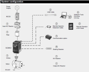
It doesn't look like there is a built-in reactor for the incoming. Omron actually shows a connection diagram in the manual. The line filter (and the reactor) is shown at the incoming side of the VFD.

Actually I am not sure what the AC (or DC) reactor is supposed to do. Can you shed some light on this?

02-08-2013 11-34-27 AM.png
 
Reactors are simply inductors which make them lo-pass filters. An input AC reactor is used to keep harmonics, especially current harmonics, and the resulting distortion from traveling backward from the VFD into the power supply network. Small drives like you have mentioned are rarely a problem so they rarely have input reactors.

Drive output lead reactors are used to block high frequency components of the drive output pulses from traveling down the motor leads and damaging the motor insulation. This is only a problem with relatively long motor leads. If the motor is only a few meters from the drive, they are not generally required.

The DC bus reactor mentioned works with the DC bus capacitors to smooth the DC that has been rectified from the incoming AC. The two form an L filter which is very good at providing a nice smooth DC voltage for the VFD output switches feeding the motor leads.

How do you know when you need an input reactor? If this depends on motor size then at what point should I get one for future reference?
 
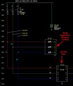
Should I also specify a surge suppressor for the incoming AC mains? One of my previous projects uses one from Phoenix Contact and the schematic shows a branching circuit (off of the mains) for this unit.

02-08-2013 2-40-46 PM.png 02-08-2013 2-48-39 PM.jpg
 
If you buy a quality VFD, there is no need for additional surge suppressors on the input side.

The need for additional filtering on the input power lines to a VFD is based on the expected harmonic content the system will generate. This is determined by a host of variable factors including front end design of the VFD, supply transformer inpedance, length of all leads in the circuit to a common point of coupling and other loads on the same circuit. Analysing this is a job for a computer and most drive manufacturers have programs that will crunch the numbers for you. But expect to have to input a lot of detail data.

Of course, you could just wing it and measure the harmonics after the job is done. Then, if they are too high, you have to go back and add filtering. I know this sounds a bit stupid but you'd be surprised at how often that's exactly how its done.
 

Similar Topics

Why there is a need of power line filter for PLC Is there a requirement of Power line filter for DC input PLC? How to chose a line filter for a PLC
Replies
0
Views
928
Does anyone know of any commercial off-the-shelf Power Line Communications gateways, suitable and interfacable with Programmable Logic Controllers?
Replies
0
Views
1,230
Hi there, Currently I'm working with PLC Mitsubishi Q series and Servo Motor MR-J4 series. All the system will monitoring using one PC that...
Replies
1
Views
1,342
I'm having some difficulty figuring out when an AC line filter would be appropriate for an application. What exactly is being filtered, the...
Replies
2
Views
2,337
hi, i have some question about the single phase line-to-line for the kinetix 2000. the manual only show that contractor using for the three phase...
Replies
0
Views
1,253
Back
Top Bottom