Omron Zen - How to imitate a while loop?

karon

Member
Join Date
Aug 2013
Location
Chicago
Posts
6
Hello,

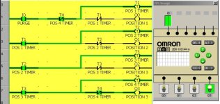
I'm trying to create a program for the Omron Zen, which, when the input is triggered, will switch from Q0 to Q3 in 5 minute increments, and then start that cycle over. I have the switching down - I just can't figure out how to loop it! Any tips?

Here is my ladder diagram:
 
Welcome to the forum.

You need to modify the input switch so that it can be "reset" by the logic to allow your code to repeat.

Since you asked for a tip, I will let you think about this instead of providing more information.

By the way, great job so far!

Let us know if you need more information.
 
I was trying to do something like that - at first I had the input trigger a work bit, and then I put the work bit in the spot where I have the input right now, to start the cycle. Then at the end of the last line, I have the work bit as an output too, but then I get some weird error about it being in two lines, and the program won't even run past the first line, so I am stumped...Do I need a counter? And if so, how would I implement it? I am brand new at this PLC stuff, so thanks for the encouragement, but just a littttle bit more help would be much appreciated!!

Thanks!
 
I have not tried this but it should work.
Try adding a normally closed contact from T4 in series with I0.
Let us know how that works. Then let us know WHY it works.
 
Basically work bits act as logic placeholders.
You also need to understand the S / R coils.

The S (SET) coil once turned on, stays on until the R (RESET) coil of the same address is turned on.

If you are familiar with a latching relay, think Latch (SET) coil and Unlatch (RESET) coil.

Does that help at all?
 
I think I have figured it out. Here is my completed program. Thanks for your tips!
Now that you have found ONE way to make it work, go back and try Gtsuport's method:
Try adding a normally closed contact from T4 in series with I0.
Which way is simpler? Do you understand how the simple method works? HINT: In the attached picture, you can see that as soon as T4 reaches its time setting, it will open the T4 closed contact on Rung 1, causing T1 to reset to 0, which causes the T1 contact on Rung 3 to open and resets T2 to 0 time and causes it contacts to return to their normal state, which causes T3 to reset to 0, which causes T4 to reset to 0. So then what happens next?

This is a continuation of Karon's previous thread:
http://www.plctalk.net/qanda/showthread.php?t=81577

Karon's 3PT Probe ZEN R1.jpg
 
Last edited:
So then T4 is reset to zero and the T4 closed contact on line 0 closes again, starting the cycle over again. Aha. I never would have gotten that. Thanks for walking me through it.
 
Yes, that is correct. It is a neat way to create a logic loop without using any new instruction addresses that you did not already have.
 

Similar Topics

I am very new so I will try to give as much information as possible. I cannot get a Prolific PL-2303TA USB to RS232 to connect to an Omron ZEN...
Replies
1
Views
1,589
Hi, after 30 years involved with automation I'm actually writing my first PLC program and am struggling a fair bit. My background is mechanical...
Replies
8
Views
1,876
Hi I am setting a system up as per the attached picture, 5 inputs that are always present. These are sensors I have in an injection mould, if...
Replies
5
Views
1,860
Hello all, new on here, and relatively new to plc programming. I am trying to write a program which counts as it receives a cycle end input, and...
Replies
4
Views
1,897
I am trying to write a program for a omron zen plc. 1st light on for 30 sec 2nd light on for 12 sec 3rd light on for 3 sec then start all over...
Replies
1
Views
1,332
Back
Top Bottom