Does anyone know the CP 342-5 profibus coupler?

Iner

Member
Join Date
Mar 2010
Location
France
Posts
190
Hello,

I have never used such system and couldn't find the answer I was looking for in the siemens documentation.

I want to use this CP with a 314 CPU (with no dp ports, just a mpi) to allow it to use the profibus protocol.

I read in the documentation that to read inputs from slave and write outputs to slave I need to use standard siemens blocks.

But how does it work with OP stations? I will have two OP73 I want to plug in the profibus network (they aren't there for the moment, so I can't test it). I have integrated them into simatic manager (not as DP slave).

Will they be able to read the CPU 314 DB's and mementos or do I need to do something to communicate through the CP342-5?
 
Last edited:
The OP73s will take care of the communication by themselves.
No need for special blocks on the S7 CPU.

A comment: The only advantage to put the OP73s on Profibus is that you get galvanic isolation and can reach further than 50 meter which is the max for the onboard MPI interface on the 314 CPU. All the data has to pass through the MPI bus via the S7-300 backplane.

Thanks a lot for this quick and very accurate answer.

Your comment is also spot on. I suggested at first putting them on MPI (as an OP is already on MPI but will be replaced by one of the newer). But the project manager/commercial sold the profibus CP as he wanted to add an ET200 rather than additional I/O on the secondary rack.

Thanks!
 
Have you considered replacing the 314 with a 315-2DP or PN version?

Is the 314 now obsolete or still well inside its "sell by date"
 
It's discontinued. It's one of these old S-300 CPU where you can't even choose the I/O adresses (they are given automatically by the position of the card)

But it's hard to sell changing a working CPU, especially when the factory is a big factory with probably enough in stock to last a while.
 
I have some example code for the Cp342-5. It has been a long time since I have used it. I don't recommend using it if you need to transfer blocks of data greater than just a few bytes. The transfers are slow because they must go over the serial buses. There were some SFC blocks that are used for synchronizing packets over the serial back plane so some programming is required.
 
Hi, I up this thread because I'v got a problem with the coupler.

I put it on the cpu rack and I connected my ET200 to the profibus. But both the ET200s and the CP are in BF.

The CP led is full red unless my PG is connected to it and then it flash in red.

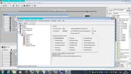
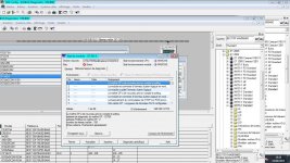
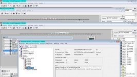
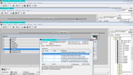
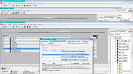
I tried to do a diagnostic detailed and I got this:

I translate from french

First pic (NCM S7):

StationNonExsitant
Message: The slave is not called by its master
Diagnostic:
The master is not in the token network

Second Pic (module state):

The DP master is now back at polling

Third picture (IM151 NCM S7):
Head module configured but not existant
Or difference between configured and existant (I checked, the reference is good and match the real one)

4th picture (module state) :

The master is now connecting at the logical token ring in Step E mode. Normal operation can resume.

5th picture (module state) :

Master has left the token ring following a bus problem due to a bus problem, a missing configuration or a false configuration. Other possible causes: reconfiguration by corresponding of passive bus.

I am a bit lost in front of all these possibl diagnostics. It looks like a bus error, but in the accessible partners, I can see the adress 10 (but I don't see what it is).

Is the error in the physical bus network, in the CP configuration, in my HW configuration, in the ET200S physical connection?

I have called FC3 block as I read that it was needed to initialize the communication...

DIAG.jpg IM2.jpg IM3.jpg IM5.jpg IM6.jpg
 
In fact, the ET200 station was not the same that I had configured, so I changed it to the right reference and downloaded the HW configuration again, but it changed nothing.
 
It is difficult to see anything on the screenshots.
But I am guessing that your ET200 station (ET200M or ET200S, or ?) is not reachable at all.
Check the dip switches on the ET200.
Check cabling and connectors.
Is it an ET200S ? In that case, is the terminator module installed at the end of the rack ?
 
Post a screenshot of the HW config of the ET200 station.
And post a photo of the actual ET200 station.

N.B. Size the screenshot and photo to max 800x450 pixels. Otherwise they will be resized automatically.
 
Hi,

I hadn't had access to the installation before today. The termination module of the ET200S is there, I see a station with the adress 10 (but it does not recognize it as a ET200S) on the bus, and the OP73 is now installed (after the et200S in the profibus network)and runs fine.

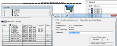
I upload a pic of the configuration. All references matches the one installed. The reference of the IM was wrong and I changed it in the configuration. I downloaded the HW configuration, I am sure of that, but I may not have dowloaded the changes in the netpro, I am not sure. Tomorrow when they stop I will download the netpro in the CPU. Could this be the cause of the error?

But what other possible errors could be the cause of the problem? Physically, the BF led is flashing and the 3 PME module on the ET200S racks have the top led red (the pwr led on the bottom is green).

et200sconf.png
 
It was the netpro.


JesperMP, I used a pdf wrote by you and found on internet about tips to use send/receiv with CP342-5.

The receiv block I tested was working fine, with NDR at 1 and no errors. But in my DB, all my inputs (lenght two octets) were at 0. I noticed that my I/O adresses start at 2 (set up automatically). I can change it manually and tried to start at 0 but I got a coordination error when I tried to download it in the cpu and changed it back to 2.

Does it mean that the 2 bytes of input I read are the 0-1 from the CP342-5 MI and that I need to read 4 bytes with receiv to get my useful inputs starting at 2?
 
You have to follow the PDF.
The last input byte is 3, so you have to read 4 bytes, 0-3.
The last output byte is 5, so you have to write 6 bytes, 0-5.

Or do as in the PDF, and start the adressing from 0. There is no reason to let the addresses follow the slot numbers.
 
It works fine. Thx for the support in this thread.

I was wondering how the Outputs of the ET200S will act if the profibus is cut. Are they reset to 0 by BF detection or do they kept their last value?
 

Similar Topics

They are installed in a control panel that was made in France and are intended for the termination of analog inputs. Each of the red capped...
Replies
3
Views
294
Need some help here (again). I tried to download my HMI to the PLC and I get this error message about a missing file. Can anyone help?
Replies
3
Views
781
Hi there, I need to work on a GE series 5 PLC which need DOS based Logic Master 5, it seems like nowhere I can purchase this software anymore...
Replies
2
Views
945
Would like to ask .. if anyone here know about creating own library or function block on ProWORX NxT ? I have a backup of ProWORX NxT project...
Replies
3
Views
1,044
Does anyone have a spare PacDrive part# LMC600CBD10000? Not necessarily for sale, but to do a bench test. I have a CF image file, and I'd like...
Replies
2
Views
1,257
Back
Top Bottom