Going round in circles

Matchu04

Lifetime Supporting Member
Join Date
Mar 2013
Location
Northampton
Posts
287
Hi guys a little help if possible.

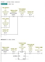
1. I have made my self a little project, of trying to control a roller shutting door, just up and down if a PEC activated. I have programmed the up and down part but for the life of me struggling with the conditional part.

I want the door to open if it detects someone. I have done this by setting a mbit to set the output. When is reachs the high limit switch it resets the mbit. After 'x' the door comes back down.

Nice and easy... That bit works sweet.

The issue Im having is when try to put a condition in. Say the PEC is trigged while the door is either up or coming down. I want to restart the timer and start counting down again, or reopen the door and start again.

2. How to i post my code so you can have a look at what i have done so far.

I dont want the answer guys just guidence of how to get there. I have spent ages trying to get it to work correctly.

Please help....
 
It is good that you have done an attempt and asks for what could have gone wrong instead of just asking for the full solution.

If your code is just a few rungs of ladder, then just post a screenshot.
If it is more than that, you can zip the PLC project and post it here for people with the same programming software to have a look.
If your PLC is not amongst the most typical, print to a PDF and post that here.
 
I couldnt find how to do it as a PDF so just attached the complete program. Please note the alarms FC aint finsihed yet.
 
Last edited:
everytime i see this many directories i am glad i am not into siemens but in codesys.
and sorry can not read S7 stuff.
 
Here's an alternative implementation. I've included a door simulator and I used a slider in plcsim to "show" the door moving.

Implementing logic like this will come with experience - I find that simulating the process helps enormously.

(Note that I've posted the blocks in a library - this reduces the size of the S7 files dramatically. Copy the blocks to your folder to download to the plc/plcsim)
 
Hi LD

I have only just managed to play with your example code as I am working nights atm. I struggled at first as I couldnt download to the blocks, but then realised that I had to copy them into the actual project, then boom off she went.

Got it up and running and I am actually buzzing off the little simulated part. When going through the code though I got kinda got stuck. I think I understand most of it just the parts below...

- In fc100 you define #bDoorUpReqeust as a parameter within FC 100 and then I think use it in a "midline coil". I think, like a marker? Have you done it this way to stop having to set and rest a mbit?

- Finally cant get my head around this

AN #sfbTimer.Q **
= #bTimerQ
CALL #sfbTimer **
IN:=#bTimerQ **
PT:=T#100MS **
Q := **
ET:= **
A #sfbTimer.Q **
FP #dEdgeStore
JCN exit

The bits with stars next to them. Why is is ("xyz".Q) It fact I dont even know what SFB4 is?

Thank you again.
 
SFB4 is the IEC on delay timer. Did you cover function blocks in your course?

I'm using the midline coil because I want to use the #bDoorUpRequest from the photocells (but inverted) in the next rung.
 
Morning

I can confirm that we covered basic fc's and fb's in my course but it was only a basic course, so we didnt cover the SFC and SFB. I need to do some more reading and will creating another thread later on to see if my understanding of some bits within S7 are correct. I would really apprecaite your input, when I do so as you obvoisly know your way around.

As for this thread, this it is the first time I have ever heard of a IEC timer, and SFB4 and I never even knew you could have a midline coil.

I have just read up a little on the IEC timers, since you have highlighted them. Most of the threads are within the forum and I can see you have had alot of input on them. Could you calrify the main reason why they are better then the normal timers. I see that you can get alot more information from them, and more flexible, there was something about scan time aswell...

Thank you again for your time..
 
SFB4 (iec ton) and SFB5 (iec tof) are iece timer. the main advantage of this timers is that they can time up to 24 (48) days, with resolution of 1ms. (it double word) they can be used as global or local, and their number is only limited by available memory. very useful things
 
With IEC timers it is easier adjust time with variable. On S5-timer you need give time base and factor on same variable (bits 12 and 13 on s5time data type)

On IEC timer you need only give time on msec format (no need to choose time factor for timer)

And if you copy program part to different project. With IEC timer you don't neeed change timer to different or take care of if you allready used timer somewhere on program. (like on original program you use s5timer T10 and on another project you have allready used T10 timer on different place)


http://www.plctalk.net/qanda/showthread.php?t=8237
 
One subtle characteristic of the S7/S5 timers is that they update asynchronously to the program scan - this means that a timer may be false in one part of the program and then true in another part within the same scan.

The number of timers available in the CPU depends on the CPU so code written using say T300 may not load into a lower spec CPU. IEC timers do not have that limitation, although you will need more memory for DB's and program for calling them.

Using IEC timers, particularly within SCL, makes it relatively straightforward to copy blocks between platforms.
 
Woooow just when you get your head round something. Something else comes along and throws a a spanner in lol.

I do apologies guys as this topic is plastered all over the forum and your probably sick to deaf of it by now, but to round it up.

An I s5/s7 is;

1- limited in the way it can be manipulate
2- timing range is limited
3- they update independently of the scan cycle, which could cause a timer to be true at the beginning or a cycle but false later on within the same cycle.
4- wastes alot of memory due to its stucture

Where as a IEC is;

1- able to manipulate easier
2- more parameters are available for a specific timer I.e current value ...
3 - timing range is much greater
4- timer is all updated when called

I think that's basically it. Would you guys agree?
 

Similar Topics

Software Ver. 22.00.00, After the 1st time of being true the EQL. instruction is still allowing the rung to be true even though the inputs are...
Replies
7
Views
220
Hello all, I am brand new here :cool:. I'm limited in my controls knowledge but always trying to learn more. I recently started working at a...
Replies
14
Views
333
I do have a problem with a GE Versamax micro PLC. By going online (on Port 1) the "OK led" goes down. Power led stays On Port 2 no reaction at...
Replies
4
Views
387
We have a 4 wire 0-10V analog OPT2012 (Time of flight distance laser) from Wenglor that we're experimenting with. We are able to teach the laser...
Replies
3
Views
536
Good Evening , We have a number of Powerflex 525 Drives . I took notice for years elsewhere and our plant , that our Powerflex 525 drive...
Replies
0
Views
636
Back
Top Bottom