Need help with thermocouple measurements

Pandiani

Lifetime Supporting Member
Join Date
Apr 2005
Location
Tz
Posts
718
Hello to all,

I have problem with thermocouple measurements in the plant. Almost all measurements in one signal cable experience sudden peaks like shown in pic1. I'm not sure how long this problem is present, but I assume very long. It was spotted only when we try to use some of the measurements in the control loops. Operators didn't notice this before, but in the last 6 months (that is how local archive is big) this is present. As you can see, there are sudden peaks in 3-5 °C in thermocouple measurements which disturb the control loops we implemented. This can be corrected with filtering but don't want to do that due to loop response and I'd like to find and eliminate the disturbance.

When I saw this it looked like to me as EM interference since almost all temperatures were affected.

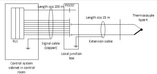
I'll explain how we measure the temperatures in our plant. The principle is shown in pic 2.

Thermocouple type K is used to measure the temperature (in this case steam) and from its head we use extension cable to the first local junction box in the field. In the same junction box arrive many extension cables from different thermocouples. From this junction box, copper signal cable is used to connect these measurements to the I/O modules of DCS. Pt100 is used to measure the temperature in the local JB so this can be compensated (cold junction compensation). This setup works very well through out the plant.
Extension cable has shield (drain) wire which is connected to the ground in the local junction box.

From the local JB we use larger copper cable type JE-Y(St)Y just like shown here: http://www.faberkabel.de/upload/datenblaetter/Datenblaetter/EN/DBL_JEYSTY.PDF

Shield (drain) wire is connected in the control cabinet to the ground and it is open on the other end (in the local junction box). So there should not be ground loop.

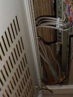
The connection to the ground is shown in pic 3. I have made the following tests:
1. I have disconnected the drain wire of copper signal cable in the cabinet (not standard solution) and connect it in the local junction box in the field, but that didn't help.
2. I have used different TC extension cable to the local junction box (without shield or drain wire connected to the ground in the JB)
3. I have connected drain wire of extension cable to the drain wire of big copper cable (this cable have as many as 10 measurements) without connecting to the ground in the JB and connect it only to the ground in the control room
4. I returned everything as originally designed (copper cable grounded in the control cabinet), while extension cable is grounded only in JB and used one free signal wire in the copper cable (I assumed drain is broken somewhere) and connect that free wire to the ground while disconnecting drain wire from the ground.
5. I connect drain wires on both ends to the ground (against the recommendation), just to check what is happening.

Nothing of these steps solved the problem (in some cases peaks were worse), so the only thing is to exchange the whole copper cable. I'm not sure how to explain this. Why this is happening only on this cable while we have very similar setups throughout the plant and it works OK? Before deciding to replace the big cable, I'd like to read your opinions on this.

Thank you!

Best regards,
Pandiani

Pic1.jpg Pic2.JPG pic3.jpg
 
Pandini,

Any junction point in the thermocouple should have special terminals for the specific type of you are using. In this case, type K. The extension cable, should also be of the same type cable. Try hooking up a type K thermocouple right to the controller input, I am sure you will see a much cleaner signal. Now try it using only type K extension cable all the way to point of use.

George
 
Pt100 is used to measure the temperature in the local JB so this can be compensated (cold junction compensation).
This is an area that you did not list as being tested. If your cold junction compensation temperature is wrong, it would effect your temperature readings. Perhaps the Pt100 is failing.
 
Are the thermocouples isolated from ground? Is one of them shorting to ground? Might upset reading on entire PLC module. Not sure if large cable goes to one or more modules.
 
This is an area that you did not list as being tested. If your cold junction compensation temperature is wrong, it would effect your temperature readings. Perhaps the Pt100 is failing.

Sorry not to mention this. Pt100 is a 4-wire measurement and it is steady. This was my first suspect (since it is used for compensation of all other TCs), but it's OK.

All thermocouples are isolated from the ground. I asked technicians to check resistance between steel tube and connection points on the head and they determined they're ungrounded (we checked only two of them on which peaks were especially high).


Probably in the next overhaul we'll exchange the signal cable. It is not an option to use extension cable all the way to the control cabinet. Like I said, this setup is widely used and we have no problems in that other cases.

George, extension cables are ordered and supplied for use with TC type K.

This thing puzzle me.
 
Last edited:
Another option is to mount as close as possible to your thermocouples transmitters, 4-20ma back to the PLC. $$$ and PLC module changes.
 
Using mA transducers is also not an option since this would need a lot of rewiring and changing I/O module. After reading your answers and suggestions. Large cable is wired to two different I/O modules for thermocouples. I'll double check all TCs to find out maybe there are some grounded ones. Maybe indeed this is the reason for these peaks.
I'll wait for the next overhaul to inspect this and make further tests.

Thank you for your suggestions.
 
short a tc in the junction box, to check if problem is in copper wire or tc cable.
if in copper cable check for a large cable running on a vfd.
200 meter is very far, for this very low voltage, check if anything changed like big motors etc.
 
This is almost certainly EM interference.

What are those light brown cables tie-wrapped less than 6 inches from your analog cables ? (pic #3).

Can you shut everything down and see if the interference goes away ?

Re-start plant sequentially and see if any particular plant causes the interference.

Ground any unused conductors in your copper cable.

I agree that 200m is a long way for thermocouple voltages.

Is there anything in the local JB that is powered from a switching voltage regulator ? Linear PSU's produce cleaner power.
 
wbt3pj.jpg


1) Why is the yellow trend near the bottom of the chart spike free? How is it different than the others?

2) The red trend has no well defined spikes. How is the red trend different than the yellow/green/blue/gray trends?

3) The chart's time axis is not labeled. What is the period of time between the evenly space spikes on the yellow curve? 0.6S? 6 seconds? 60 seconds?

What is the duration of the spikes? The trend appears to show a single point up or a single point down. Are these transistions 1 second in duration?

It's odd that you catch so many single point excursions, one would expect that an aliasing effect would show 'growing' then 'shrinking' spikes as the sample-hold catches the spike at different levels.

4) >(we checked only two of them on which peaks were especially high).

If your input card is single ended, one bad apple can spoil the whole bunch. KeithKyll alludes to this, as well. Common mode appears as an offset, which is what you're seeing. Do pursue your check of the remaining T/C's.

5) What is the receiver end? How many inputs on the AI card? Do all these T/C's go to the same AI card? Brand? Model?

Are there other T-C's on the AI card with these spikey inputs?

6) Is the copper extension wire for these spikey signals twisted pair cable?

7) What other cables run in the 200m tray from the junction box back to the AI's?
 
wbt3pj.jpg


1) Why is the yellow trend near the bottom of the chart spike free? How is it different than the others?

This yellow line is cold junction temperature in the junction box measured by 4-wire Pt100.

2) The red trend has no well defined spikes. How is the red trend different than the yellow/green/blue/gray trends?
Red line is temperature from another cable but measure the twin temperature since we have two identical steam systems (we have two drums) in the thermal power unit.

3) The chart's time axis is not labeled. What is the period of time between the evenly space spikes on the yellow curve? 0.6S? 6 seconds? 60 seconds?
The total time is 30 minutes. Each division is 5 min wide.

What is the duration of the spikes? The trend appears to show a single point up or a single point down. Are these transistions 1 second in duration?

I think duration of the spike is about 2-3 seconds.

It's odd that you catch so many single point excursions, one would expect that an aliasing effect would show 'growing' then 'shrinking' spikes as the sample-hold catches the spike at different levels.

4) >(we checked only two of them on which peaks were especially high).

If your input card is single ended, one bad apple can spoil the whole bunch. KeithKyll alludes to this, as well. Common mode appears as an offset, which is what you're seeing. Do pursue your check of the remaining T/C's.
I will.

5) What is the receiver end? How many inputs on the AI card? Do all these T/C's go to the same AI card? Brand? Model?

AI card is actually FUM232 module for Siemens SPPA-T2000 system. It is used for both Pt100 and TCs. It can store 14 Pt100 measurements or 28 TC measurements. The datasheet can be found in attachment.

Are there other T-C's on the AI card with these spikey inputs?

No, and I tried to exchange the AI and that didn't solve the problem.

6) Is the copper extension wire for these spikey signals twisted pair cable?

Extension cable from TC to the junction box are ordered just for type K TCs. From junction box to the control cabinet is copper cable like shown in datasheet attached above.

7) What other cables run in the 200m tray from the junction box back to the AI's?

Actually, the length is about 130 m, I wasn't really sure at first.

All cables in the control cabinet are the same type, including those brown cables in the picture.
 
Those are longer than 3 seconds. More like 15-30 seconds. This isn't noise. It's too repeatable. Almost all spikes start with a downward trend, then upward, then flat line.
The red line that you say is normal isn't that much different than the "spikes". If you doubled the PID gain parameter on the "good" red line,
you might get the same reaction as the others.
The green trace is different. It has some that are downward only. Temp dived, then recovered, as if power was lost, then restored.
Scenarios:
1) Loss of power.
2) Command for heat goes full.
3) Power returns.
4) PID has one overshoot, then recovers to flat line.

or
1) Somebody opened the door. Interlock keeps heater off. Cooled.
2) Door closed. Heater returns with too much gain - overshoot.
3) PID recovers.
Add something to track trends, like another (paper?) chart recorder.
 
Last edited:
Hello Keithkyll,

the disturbance are different in amplitude and duration. This is a small extract:
7:22:00 543.205 7:22:01 543.205 7:22:02 543.205 7:22:03 543.205 7:22:04 545.267 7:22:05 547.330 7:22:06 547.330 7:22:07 546.166 7:22:08 543.450 7:22:09 543.450 7:22:10 543.450 7:22:11 543.450 7:22:12 543.450
7:23:53 544.455 7:23:54 544.455 7:23:55 544.455 7:23:56 542.729 7:23:57 540.990 7:23:58 540.990 7:23:59 542.159 7:24:00 544.915 7:24:01 544.915 7:24:02 544.915

These are temperatures of superheated steam, so sudden changes are very uncommon. At first I thought some of the measurements are too close to the nozzle and get hit by spraying water, but that's not the case, because on the twin system this doesn't happening and it cannot be on all temperatures. The only thing in common to these temps is that they're all in the same cable (going to two different AI TC cards).
In the attachment you can find two of these temperatures (yellow and green) in log from this morning.

Probably, during next overhaul we'll exchange the long signal cable as final try. I'd like to be sure that this is EMI since during the stop of the unit (all 6 kV nearby drives OFF) I noticed spikes as well. If I manage to find, I'll attach this trend also.

Thank you for the help.
 
the spikes are below 1 % of the normal reading and 0.5% of full scale, so stop any thinking and check if twin system has its filter on and this one is direct, It is very common the temps have some noise on the lines, and that the readings vary a few bits. so stop searching for trouble it is fine mighty fine.
 
...
I'd like to be sure that this is EMI since during the stop of the unit (all 6 kV nearby drives OFF) I noticed spikes as well. ...
It is definitely not EMI. EMI is on the order of milliseconds.
You have the same temperature for several seconds. On the text attachment, the upset durations are even longer.
Most are negative first. Most are followed by a positive shift.
Toroids, capacitors, and digital filtering are not going to make this go away.
In your first post, you said some of the steps you took (lifting drain wires) made the spikes worse. Please elaborate or post a plot. Is the digital filtering on the PLC making EMI noise events look like this? I'd be very interested to see how real noise is plotted.

I'm leaning towards mechanical. I don't know what. My first thought is the readings are real.
You're convinced it's noise in the cable. Okay, let's prove that first. Read and graph temp at the JB (Cold Junction box) to verify. Can you disconnect a TC for 10 minutes or so without upsetting the system? A 5 minute plot at JB, followed by a 5 minute plot at PLC should be enough.
 

Similar Topics

hello all.! im just new here.. im searching how to know if my plc has its input module for thermocouples till i reached this page.. my problem is...
Replies
10
Views
3,701
I'm fairly new to Rockwell software, I've had some basic training in the past but nothing too advanced. My company and I use Reliable products for...
Replies
11
Views
282
Hi all, I am having issues accessing my Cimplicity software - the site code changed after re-install and I am no longer able to attain a new key...
Replies
10
Views
158
Good day all! Can someone help me with the procedure to update Beijers E700 firmware? The Panel I am working on is firmware 2.04v and I would...
Replies
1
Views
62
Back
Top Bottom