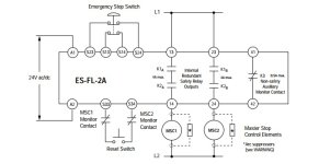
about the internal wiring of a typical safety relay.

unsaint32

Member
Join Date
Oct 2012
Location
minneapolis
Posts
365
My understanding is that the S13 & S14 circuit has 24V+, and S23 & S24 circuit has 0V. And the K1 ... Kn coils energize only when the two circuits are closed. So, here are my questions.

Q1) I get 24V across S13 & S23 as I am supposed to, but why can't I get 24V across S13 terminal and the source GND?

Q2) Between S13 & S14, which is the source side?

Thanks.
safety_relay.jpg
 
S13& S14 are termed channel 1
S23 & S24 are termed channel 2

These channels are not referenced to ground. They supply a voltage from their own internal supply and ground reference (the easiest way to view these channels is as supplies to volt free contacts - ie your e-stop p/buttons). S13 supplies a signal to your e-stop circuit which if made returns that signal back to S14 - Ditto S23 & S24 only when both channels are ok do the output relays fire (these channels have to be made together within 250mS)

This is a very simplified explanation of a very basic safety relay

Check out and Google Pilz safety relays for further explanation.

Steve
 
Let's state that any Sxy marked contact of any Safety Relay does not carry any "user measurable" electrical circuitry "quantities" unless internal relay contacts "fed" by user circuitry to be "safely controlled".
Whatever you are DMM "measuring" between S marked Input contacts is not what the DMM displays and you cannot approach troubleshooting the way you'd do it on a "generic" electrical circuit.
The S marked Input contacts of any Safety Relay are actually carrying manufacturer specific "pulse forms" some of which will never be "detected" by a common DMM measuring approach; I have replaced quite a few burnt up relays after DMM troubleshooting ("I don't know what happened?...I put my meter on the cable end and there was no power...It never sparked when I cut it or shorted the wiring...").
You will have to go "cold" when troubleshooting/verifying safety circuitry(no power within the safety system); circuit continuity ("Zero" Resistance) is the only measurable circuit value that matters.
 
Last edited:
You will have to go "cold" when troubleshooting/verifying safety circuitry(no power within the safety system); circuit continuity ("Zero" Resistance) is the only measurable circuit value that matters.

I cannot read voltage between s13 & s23 in some safety relays?

By "cold," you mean I must shut down the system and use ohmmeter?
 
Yes.
Turn the Safety System power off (Safety Relay supply power); use an Ohmmeter and verify the continuity of the circuits connected to the S marked Safety Relay contacts.
 

Similar Topics

I installed a small expansion card for a S7200, 4*DO, and it need voltage on eight places! Why couldnt siemens supply this internally... should...
Replies
3
Views
1,491
The client has an application that when communication between the PLC and the Factory Talk VIEW supervisory fails, the object in the supervisory...
Replies
5
Views
279
Hello everyone; I have Mitsubishi PLC FX3U 32M in hydropower plant governor, an error message popped up when a technician was working on an...
Replies
2
Views
361
Kindly, we are having a problem on a machine during night shifts, while no engineering tool is online. So, we were thinking of programming some...
Replies
9
Views
757
Hello. If anybody has seen this before and could provide some clues I and some other people would be extremely grateful if you can share such...
Replies
2
Views
1,326
Back
Top Bottom