1746-nr4, rtd issues

RonB

Member
Join Date
Feb 2012
Location
Hickory
Posts
36
This is my first run in with this setup. I've been all through the forums here searching for any information I can latch onto.

Reading through the manual for a 3 wire pt100 setup, it looks like rtd 0 and sense 0 are running together and your measurement is returned on "return 0."

I have 110 ohms of resistance between either of the probes red wires to the white wire and none between the red wires. Maybe I'm wrong in assuming (as we all know what that does) that rtd 0 and sense 0 be hooked up to red/white and return 0 be hooked up to the remaining red wire in the rtd?

I believe after looking through the manual as well as earlier posts that I have the channels configured properly, but I only see a static reading.
*note: this setup is currently using a 3 foot long shielded cable from my desk to our test board.
I've also attached the rss of the test program I'm using.
 
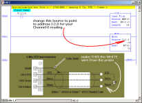
not sure that I understand everything that you're saying - but try hooking WHITE to "Ch 0 Return" ...

quick question for you:

do you understand WHY there are two wires (the red ones) that just run in parallel out to the probe? ...
 
and from a QUICK look at your program - it seems that you're taking the signal from the wrong address for your Channel 0 data ...

try using the address I:2.0 for the Source of your MOV instruction ...
 
if i understand correctly the rtd uses 3 wire so that it can get a more accurate reading by comparing the resistance values of both of the wires. please set me straight if my thinking is too far off into left field.

I changed the the source of the mov file and now I'm getting a reading.
 
you're correct in the use of the three wires ...

the basic idea is that the resistance of the wires between the PLC and the probe will always have SOME effect on the signal from the RTD ... if the wires are LONGER then there would be MORE effect on the reading ...

so ...

the EXTRA wire is used so that the system can "read" the amount of resistance from the wiring (without including the sensor's wiring) – and then COMPENSATE for that built-in resistance when it makes its temperature reading ...

notice there's a "gotcha" in the way the Configuration screen is set up for the module ... on the tabs, the "channels" are numbered 1 through 8 ... but the data tables are numbered 0 through 7 ...

so ...

it's VERY common for technicians to be tracking down (or modifying) the WRONG signal while troubleshooting a system – because the numbers are "off-by-one" depending on which part of the software they're looking at ... (gotcha!) ...

well, now that you're looking in the right data location you're seeing a reading ... but unless you've got the wiring connected correctly, the reading MIGHT be just the resistance of the wires – and NOT the resistance of the sensing probe ...

does the data reading change when you heat/cool the probe? ...

.

rtd_wiring_address.PNG
 
Last edited:
it is actually I:2.1
when I found this card on the shelf it had a jumper setup on channel 0 so I used channel 1 on the card. (I have channel 2, in the advanced configurations, configured and enabled)
I can definitely see where the "gotchas" come into play. Troubleshooting a large system would definitely get confusing.

The raw reading on the input does go up and down with heat applied or removed. If this was backwards, I would only see a static resistance value of the wire correct?
 
(I have channel 2, in the advanced configurations, configured and enabled)

not in the program file that you posted ...

anyway – I've got to get back to work ... I hope that this has been helpful ...

good luck with your project ...
 
I did not mean to come across as I know better, what I should have said was after we spoke of the gotchas and you mentioned changing the input address I did make the appropriate changes to the correct channel.
Thank you for taking the time to help me out I really do appreciate it.
 
I did not mean to come across as I know better,

I assure you that I did NOT take your comments that way ...

Thank you for taking the time to help me out I really do appreciate it.

you're quite welcome ... I seldom have time to contribute to the forum these days –fortunately (I prefer to say "blessedly") my work schedule keeps me too busy to help much ... I happened to have a few minutes here and there this morning – but now I have deadlines pressing ... it sounds like you're well on your way – and I was completely sincere in saying that I hoped I had been helpful to you – and I do sincerely wish you the greatest success with your project ...
 
I seldom have time to contribute to the forum these days –fortunately (I prefer to say "blessedly") my work schedule keeps me too busy to help much ...
Ron, you could do like I did years ago and retire from work, then spend all day on this forum when you get the urge. I can't say that if I could go back and do it over, that I would choose to spend the past 20 years working!

The only thing is that when you retire, like many others you may lose all desire to see or do anything that reminds you of your previous work! Fortunately that did not happen to me.
 
Greetings Lancie ...

up until a few days ago, it had been about four months or so since I'd posted anything here ... I made myself cut back when I realized that I had been spending an average of two or three hours a day on the forum ... I've got other fish to fry ...

anyway ...

my pie-in-the-sky dream right now, is to sell off the business – and then to keep working for another year or so getting the next owner up to speed ...

I'll be 67 years old in another couple of months – so now's a good time to sell ... I've talked to a few guys who have been interested – but nothing definite so far ... I'm afraid that if I don't sell out before I die, then I'll just leave my lovely wife with a truckload of training equipment – rather than with a nice little chunk of change ...

personally I'd prefer to just keep right on working until I drop – but I've got to look at the responsibilities of what will happen when I'm gone ...

anyway – I'm spending quite a bit of time getting the loose ends tied up and squared away for any new owner who might come along ...

so – thanks for your thoughts ... now back to work ...
 

Similar Topics

If anyone has one they'd like to sell, please PM me. Alternatively, if anyone has two temperature transmitters (4-20mA), please do the same. The...
Replies
0
Views
1,285
Good day all. I have an RTD module for a SLC500 5/03 that I can't get the temperature values to stop jumping from one temp to the next, on the HMI...
Replies
16
Views
4,660
I need help in identifying the fault with a 1746-NR4 RTD / resistance module. The hardware is a SLC500 1746-NR4 module inserted into slot 3 of a...
Replies
0
Views
1,283
Hi,, I used 1746-NR4 module with 1000 ohm potentiometer. How to connect potentiometer to the module and how to configure it? Thank you for help...
Replies
1
Views
3,076
Hi Just programming and configuring an 1746-NR4 card for an SLC system on the Configure box drop down menu for Types of Input I have 2 sorts...
Replies
8
Views
13,940
Back
Top Bottom