micrologix 1400 thermocouple input card

irondesk40

Member
Join Date
Jan 2008
Location
nc
Posts
630
i have testing controlling temperature using a micrologix 1400 and the Allen bradley 4 channel thermocouple input card. not in the office so do not remember the exact part number. I have found that if i have all the channels on a card enabled and do not have a thermocouple connected to it then i can see noise being induced into the value coming from the thermocouple itself. I have been using grounded thermocouples and have a ungrounded being shipped to me for testing.
I know you can go into the advanced configurations for the thermocouple card and enable or disable each channel. what i see happening is machine is built with thermocouples connected to each channel and for some reason breaking etc. in the plants. what i have done is set the input to upscale when a thermcouple is not connected and then doing a compare in the program. If i see the value too high then i set a heater fault memory and disable the output going to the solid state relay. Is there a way that if you see this fault to disable the channel input the same way that you can from the advanced configurations with rslogix 500? I have read the manual and not sure. Anyone ever accomplished this and would share would be greatly appreciated. I did leave a message with ab tech support last friday but not got a reply yet.
Thanks
 
Is there a way that if you see this fault to disable the channel input the same way that you can from the advanced configurations with rslogix 500?
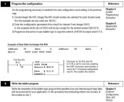
I think there is a way to disable a channel from within a program. In older Analog Input cards for the SLC500 PLCs, this was done by writing to bits within the "Output" word that was always associated with the Input word for that particular analog input channel. For example, if I had the 1746-NT4 Thermocouple/MV Input module in Slot 1 of my SLC, I could move or copy a word (with bit 11 set to enable the channel) to O:1.0 to set Analog Input Channel 0 to be enabled or disabled (along with all the other TC parameters that also could be set). Here is an example from the SLC 500 4-channel Thermocouple/mV Input Module User Manual (see attached picture).

Note that the COP in the program writes to the Output word O:1.0 for the Input channel I:1.0 that is being configured.

It appears that the MicroLogix 1762-IT4 Thermocouple/MV Input Module may use the same setup, except no mention is made in the manual of being able to configure it except using the built-in configuration routine, although the 1762-IT4 User Manual on page 3-4 says that the configuration word is both readable and writable. It just doesn't say what the address of the configuration word is exactly. A guess is that it has to be the same as for the old SLC500.
Channel configuration data for the module is stored in the controller configuration file, which is both readable and writable.
For the 1762-IT4, bit 15 is the Channel Enable bit, 1 = enabled, 0 = disabled. You could test the method by writing a 0 to bit O:1.0/15 on the First Scan, where "1" is the slot that your module is in, then go to the configuration screen and see if Channel 0 is disabled.


Thermocouple Module Configuration within Program.jpg
 
Last edited:
I think there is a way to disable a channel from within a program. In older Analog Input cards for the SLC500 PLCs, this was done by writing to bits within the "Output" word that was always associated with the Input word for that particular analog input channel. For example, if I had the 1746-NT4 Thermocouple/MV Input module in Slot 1 of my SLC, I could move or copy a word (with bit 11 set to enable the channel) to O:1.0 to set Analog Input Channel 0 to be enabled or disabled (along with all the other TC parameters that also could be set). Here is an example from the SLC 500 4-channel Thermocouple/mV Input Module User Manual (see attached picture).

Note that the COP in the program writes to the Output word O:1.0 for the Input channel I:1.0 that is being configured.

It appears that the MicroLogix 1762-IT4 Thermocouple/MV Input Module may use the same setup, except no mention is made in the manual of being able to configure it except using the built-in configuration routine, although the 1762-IT4 User Manual on page 3-4 says that the configuration word is both readable and writable. It just doesn't say what the address of the configuration word is exactly. A guess is that it has to be the same as for the old SLC500.

For the 1762-IT4, bit 15 is the Channel Enable bit, 1 = enabled, 0 = disabled. You could test the method by writing a 0 to bit O:1.0/15 on the First Scan, where "1" is the slot that your module is in, then go to the configuration screen and see if Channel 0 is disabled.

could not figure out how to do it with the micrologix. for example i have a thermocouple card that is address as I:2.0.
If you look at the data file it will show I:2.0-2.5
I also have another thermocouple input card that is addressed as I:3.0 and it does the same thing if you look at the data file it will show I:3.0-3.5
I then have a output card installed and it addressed it as Output 4.0.
It will not show the output 2.0- 3.0. I called tech support and they told me that the micrologix does not have a corresponding output data file that you can access in the software. Basically told me i would have to switch to a compact logic or different processor to be able to enable or disable in the software.
I was going to do the first scan for outpout 2.0, but it does not reconize it as a legit data file.
Hope i described it good enough to understand. Thanks
 
Thanks for the feedback. You explained it well.

It would have been nice if they had mentioned in the 1762-IT4 manual about which PLCs had the ability to write to the config file from within the program. I guess Rockwell figured that by the time you found out, you would have already bought the PLC and the TC module, and it would be too late to get your money back!

It will not show the output 2.0- 3.0....I was going to do the first scan for outpout 2.0, but it does not reconize it as a legit data file.
That would not be a valid test, because for the old 1746-NT4 Thermocouple module for the SLC 500's, RSLogix would not show any Outputs for the Input card or indicate that they existed in any way, but it would allow you to copy or move a data word to those non-existent "phantom" output addresses.
 
Last edited:

Similar Topics

Hey all, first time poster here. I am wondering if anyone has tried using a Keyence SR-X300 barcode scanner to a Micrologix 1400. Keyence sent...
Replies
0
Views
30
I'm using a SLC typed write from the ControlLogix5572 to the MicroLogix 1400, with path: 2, (MicroLogix IP). The ControlLogix equipment has a...
Replies
0
Views
91
Hi, I am working with a Micrologix 1400 model 1766-L32BXB. With no input wires connected to the “in12” thru “in19”, I am getting 24 volts while...
Replies
4
Views
221
Hi everyone, I hope I don't butcher this up, please feel free to critique me wherever if I do, I have an issue I would equate to "chasing...
Replies
4
Views
301
Hi everyone, I'm working on a project where I need to exchange data between a Siemens S7-1200 PLC and an Allen-Bradley MicroLogix 1400 PLC. The...
Replies
8
Views
651
Back
Top Bottom