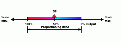
PID control output when PV = SP

unsaint32

Member
Join Date
Oct 2012
Location
minneapolis
Posts
365
I am practicing temp controller setup with E5CN R2MTD 500. My parameter values are; Control type=PID, Control period=10 seconds, Proportional band=30, I=45, D=8. When the PV is at the SP, the output is ON for just a little over 1 second. I thought that the output will be on 50% of the control period when the PV is at the set point. Why am I not getting the output ON for 5 seconds? A gain issue? I don't know how to even set the gain value with E5CN.
Thanks.
 
When the SP = PV, the output will be determined by the amount of integrator build up that is present, possibly modified by some derivative action on a SP and/or PV change.

In any event, your theory isn't correct at all, with 0 integral and 0 derivative action, if the SP=PV, then by definition, the error is also 0, and even with an infinite proportional gain, the output would be 0, no 50%.
 
I read few sources that says 50% output when pv=sp. Here is one. http://iseinc.com/what is pid.htm

What am I not understanding?

Thanks.

I didn't see anywhere that the site said that the output would be 50% when the PV=SP.

With a good application of PID control which includes the proper sized control element, be it a valve, heater, etc. The only two control outputs that you wouldn't want to see for long periods is 0% or 100%. If normal, steady state operation puts you at either limit, there is probably something wrong and it probably isn't steady state.

Beyond that, PID control outputs will assume (be changed to) whatever value is required to maintain the PV at the SP. The idea that when PV=SP the output will be either 0% or 50% are *both* misunderstandings of how proportional control works, regardless of the equipment involved.
 
...What am I not understanding?...

That is such a tough question to answer! (Also tough to not answer!)

However, when PV = SP the output will be whatever it takes for the PV to be maintained at SP. When those two are equal a proportional only loop will quit changing the output. That value will vary. For example, on a cold winter day the output to a steam valve for heating may be nearly full open to get enough steam into the system to maintain heat. On a moderately chilly spring day the heat may be maintained with just a little steam and the valve may be barely cracked open.

Look at it this way - if the output was always 50% when SP = PV then you wouldn't need a control loop, would you? You'd just set the signal at 50% and go have a beer!
 
what does the 50% output at the setpoint signify then? I always thought if the gain is 1, then when the PV is at the 50% mark of the proportional band, the CV is at 50% of its range. Thanks for all your replies guys.
 
What does the 50% output at the setpoint signify then?
In the graphic that you posted, the 50% represents (very poorly) the Setpoint, not the Output. Actually there should be two scales, one for Setpoint and one for the Output. For their own theoretical training purposes, they chose to show both Setpoint and Output as 0 to 100%, and the present Setpoint halfway between the limits of the Output. The Setpoint could be anywhere in between. Most likely in the real world the Setpoint would be calibrated to read some engineering unit such as "Degrees F" or "PSI" or "RPM", something like that.

The Output (for that Setpoint (SP) of 50%) is shown as 0 to 100%. We don't know what the Output for a Setpoint of 50% will be at any time, because as Tom said it will depend on many factors and will vary up and down between 0% and 100% to keep the Process Variable = Setpoint.

The Setpoint and the Output often do not even have the same units, unless both have been scaled to 0-100% (per cent) as in this example. In other words, if the Setpoint was in Degrees F, its range might be 32 to 80 for a heating unit, and halfway or 50% would then be "56" Degrees F. But the Output might be a current that ranges from 4 to 20 miliamps, with 50% being "12" miliamps. So in this case 50% Setpoint = 56, but 50% of the Output = 12, but that doesn't tell you much because one is apples and the other is oranges.
 
Last edited:
In a classic PID calculation, the P part is simply:

CVp = (SP - PV) * GAINp

Where CVp = the control output from the proportional term,
SP = Setpoint
PV = Process Variable
GAINp = Proportional term gain.

Nowhere in there is a 50% (or 25%, or 3.2192%) offset.

The overall output of a classic PID equation is the sum of the proportional term, the integral term, and the derivative term. Of the three, only the integral term can have any possible output if the SP and PV are equal, since the integral term is based on the past error over time.
 

Similar Topics

i have a control valve that is used to heat a tank of water. the steam valve only has digital signal to control it and no position feed back. when...
Replies
4
Views
2,721
Hello All! I have a PLC5 which is controlling a cocurrent drying process through a rotary kiln. I believe the control stategy of using an outlet...
Replies
11
Views
12,163
I am working with a FB 58 TCONT_CP with sample time set to 1 second P GAIN set to 10, I to .13, D to .79. I am controlling a process...
Replies
2
Views
2,059
I am Using SLC505 Processor To Control Flow and Pressure. I am using Flow and Pressure Transmitter. I would like to use dual PID to contol one...
Replies
3
Views
1,825
hi need to install a pt100 in my machine and want to control it from PLC pid.When I downloaded FB 41 and 43 into cpu it goes to off and doesn't...
Replies
0
Views
2,114
Back
Top Bottom