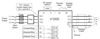
Omron v1000 drive wiring braking resistor

unsaint32

Member
Join Date
Oct 2012
Location
minneapolis
Posts
365
The B1 and B2 terminals are for thermal relay AND for braking resistor. Doesn't this mean if the thermal relay trips I have no dynamic braking? I just don't see the advantage of this wiring configuration.

omron v1000 wiring.jpg
 
They want you to install a fuse to keep the resistors(and other things) from catching on fire. Yes, you will lose dynamic braking at that point and the drive should trip on high DC bus voltage when it tries to brake and it needs the resistors.
 
Last edited:
That's not a motor or drive thermal switch but one mounted in the brake resistor housing. If the brake resistor has been sized too small or the braking energy is unexpectedly too high or if the cooling air is somehow cut off to the resistors, then the switch will open and save the resistors or prevent a fire.
 

Similar Topics

the parameter is for motor rated current. The range is 10 - 200% of drive rated current. But the actual value is displayed something like 0.8...
Replies
2
Views
1,681
HI; i have in stock PV1000 DH+ ,and i want install this PV with OMRON plc CS1J CPU44; is there possible ? if is ok ;please descript a...
Replies
8
Views
2,765
Hi all, Currently having trouble getting a speed reference to write over modbus to an Omron M1... I can successfully write a run command and...
Replies
6
Views
214
Hi There, I have couple of Omron PLCs connected on my kepserverex and my intouch reads data from kepserverex. I have been observing that roughly...
Replies
4
Views
130
Hi dear . I have a system with cj1m cpu11 etn. previously NT 5z HMI was connected with plc. recently my old HMI got damaged. I want to replace it...
Replies
12
Views
233
Back
Top Bottom