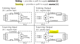
Does this connection diagram make sense?

Tofo

Member
Join Date
May 2013
Location
CA
Posts
57
I am following an old electrical PLC design to make my machine. I think the diagram is not right. However, the machine has been built and working. I am not sure whether my understanding is wrong or some people fixed the machine after the drawing.

According to page 12 of http://literature.rockwellautomation.com/idc/groups/literature/documents/td/1769-td005_-en-p.pdf

The PLC has 16 sourcing digital output.

Note: I also find some information in Rockwell knowledge base question # 524618

My questions are
1. If it is sourcing output, should the light tower be NPN instead of PNP?
2. Would it be OK to switch the connection of the 2 RED arrows +V to GND and COM0 to 24V to make the output from Sourcing to Sinking?
3. Why the SSR work? It always has A1 connect to 0V. No matter what the PLC output, it has either no potential difference or negative potential difference

Please help
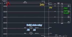
plc help.jpg
 
OK, one q: at a time.
If the PLC output is sourcing, the driven device is sinking.
So, the driven device(s) should all share COMMON..which, in your drawing, they do.
The only minor mystery is the SSR. Some SSR are not picky. A1, A2, you pick...common or positive. Either way, the devil-in-the-details is the manufacturer data for the SSR.
 
The diagram is fine. It shows a proper application of 'sourcing' outputs.

Looking at your other posts you seem to still have problems with the concepts of 'sinking' and 'sourcing'.

No, you can't reverse the power (unless, of course, you like buying PLCs). The PLC's power must be exactly as shown in the official diagrams.

The terms 'NPN' and 'PNP' are only correctly used when applied to solid-state DC switching devices. The lights are wired to the common (negative) side of the circuit thus are described as a 'sinking' load which is a proper match to a 'sourcing' output card.
 
Last edited:
Please give me some advice of my cheat sheet

Sourcing PLC output
- should connect to Sinking Output device (e.g. light tower)
- One end of the output device should connect to power supply and the other end should connect to PLC
- when the rung is true, the sourcing PLC will generate low voltage (0V)

Sinking PLC output
- should connect to sourcing Output device (e.g. light tower)
- One end of the output device should connect to GND and the other end should connect to PLC
- when the rung is true, the sourcing PLC will generate high voltage (24V)
 
Let's start with the 'cheat sheet'

Sourcing PLC output
- should connect to Sinking Output device (e.g. light tower)
- One end of the output device should connect to GND and the other end should connect to PLC
- when the rung is true, the sourcing PLC will switch high voltage (24V)

Sinking PLC output
- should connect to sourcing Output device (e.g. light tower)
- One end of the output device should connect to power supply and the other end should connect to PLC
- when the rung is true, the sinking PLC will switch low voltage (0V)

Now I'm going to make a huge guess concerning your confusion.

You have learned that, in good conductors, electrons flow freely and are the carriers of power from the negative terminal of the battery through the load to the positive terminal. Therefore, the negative terminal must be the 'source' and the positive terminal must be the 'sink'. Am I close to your understanding?

WELL FORGET IT - at least as to the 'source' and 'sink' nomenclature.

Back when 'electricity' was first being studied they came to the conclusion that there was a flow of 'something'. This was the late 1700's and 'electrons' were not known. They were able to define a 'negative' and 'positive' with regard to DC sources. In a 'flip-of-the-coin' decision the 'flow' was defined as emerging from the positive end of the source, flowing through the load, and finally going into the negative end of the source. A switching device which switched power on the positive end of a load was called a 'sourcing' device and one which switched power on the negative end of a load was called a 'sinking' device.

Will this change because we now know about 'electron flow'? Well, it hasn't in about 100 years since electrons were discovered so I'm not holding my breath. I think you're just going to have to deal with it like the rest of us.

But electrical power is not just carried by the flow of electrons. In other type of conductors the reverse flow of 'holes' is the primary carrier of power. And in free space crossed electric and magnetic oscillating fields, each one generating the other in an interesting power dance, carries power from one place to another, possibly as light, or as radio signals. So don't get enamored on 'electron flow' as the only way to describe power flow.

I hope this helps.

It is a good piece of knowledge and the corrected cheat sheet is just like a Christmas gift to me. Thanks and so helpful

I was confused of the term PNP, sourcing, rung is true @ souring/sinking , high voltage @ sourcing output relate to TRUE/FALSE. The cheat sheet give me a solid stone for me to rely on when I need to think of any PLC connections.
 
One more question.
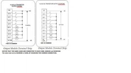
According to the NEW attached picture from a literature. The 'Common' is connected to high voltage. Does 'Common' mean anything in PLC circuit? Shouldn't it always be 0V? In the first attached wiring diagram, the COM is 0V. It is opposite to the new attached picture. Why?

Capture.PNG
 
'Common' in this usage is a terminal which connected to a number of input or output circuits. It is 'common' to all those circuits. This is in contrast to having two terminal connections for each output (which do exist and are usually labeled 'isolated outputs')

In the case of relay outputs the 'common' connection can actually be of either polarity. Similarly, some of the input circuits can also be connected either way (usually labeled as 'sink/source'). Whichever polarity of source is wired to these type commons determines the usage for all inputs in that connected group.

Oh, and note that the arrows in the diagrams are indicating the 'classical' current flow as I described in my historical narrative.
 
Last edited:
'Common' in this usage is a terminal which connected to a number of input or output circuits. It is 'common' to all those circuits. This is in contrast to having two terminal connections for each output (which do exist and are usually labeled 'isolated outputs')

In the case of relay outputs the 'common' connection can actually be of either polarity. Similarly, some of the input circuits can also be connected either way (usually labeled as 'sink/source'). Whichever polarity of source is wired to these type commons determines the usage for all inputs in that connected group.

Oh, and note that the arrows in the diagrams are indicating the 'classical' current flow as I described in my historical narrative.

These are basic concepts, Bernie, but it is amazing how often they are ignored. In my continuing education classes I frequently encounter the misconception that "common" is the same as neutral or "-". I've even had electricians in the field try to tell me they could use white for "line" because it was wired to the common terminal on a group of limit switches! It's amazing how a simple term can cause so much confusion.

I also explain that electron flow is in the opposite direction of the convention of current flow. I think at least half the class doesn't believe me.
 
Radio Shack used to have a basic electronics book by Forrest Mimms (70's??), it taught the "hole flow" vs. "electron flow" as well r/c circuits, transistors, mosfets, etc. That book went a long way in getting me started in electronics.
I would highly recommend it to anyone who could get their hands on a copy.
 
"1. If it is sourcing output, should the light tower be NPN instead of PNP?"

In this case, the light tower is a DC LOAD, it is not NPN or PNP. It can be powered from a Sourcing output card or a Sinking
output card. The 16 sourcing outputs are exactly analogous to relay outputs, but rather than physical contacts, they use a
transistor junction to provide +Vdc and current flow to the output terminal when turned on. The loads are already supplied
with a common -Vdc connection.

Irregardless of output card type, THE ELECTRICAL BURDON PLACED ON AN OUTPUT CARD TERMINAL IS A LOAD, not a switch.
There is no PNP/NPN load. These terms (NPN/PNP) refer to the type of two different transistors that are used as electronic
"switches", and are the basis for the reason sourcing and sinking of transistor type output to PLC type input becomes
necessary.

A sourcing input device (PNP SENSOR output) requires a sinking DC PLC input card.

A sinking input device (NPN SENSOR output) requires a sourcing DC PLC input card.

The same is not true for DC outputs. As you can see from the picture, the SAME LOAD is connected to
each type of output card. The load is neither PNP or NPN. The polarity of the source voltage is the
only change necessary to accomodate the same load connected to either card. The load does not sink
or source, only the PLC output does.

PN.jpg
 

Similar Topics

I'd like to connect my laptop AND proface HMI to an SLC 5/04 1747 L541 so I can look at the bit address of some of the HMI buttons. I don't have...
Replies
14
Views
6,247
I am trying to connect with a Schneider plc which has a firmware version only available in Somachine v4.2. In Machine expert After taking upload...
Replies
0
Views
95
They are installed in a control panel that was made in France and are intended for the termination of analog inputs. Each of the red capped...
Replies
3
Views
274
So, I'm really just trying to get some experience by practicing with arrays. I'm using studio 5000 v33. I have one rung with an XIC bit that's...
Replies
5
Views
224
Back
Top Bottom