ABB ACS350 Drive Dynamic Braking

Join Date
Nov 2011
Location
Ireland
Posts
182
Hello

i am trying to set up my ACS350 to dynamically brake a high inertia load.

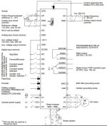
i have noticed that there are a number of digital inputs that can be used to activate the drive remotely. see attached image

i am not sure how to set up the drive to dynamically brake a load. there is a start/stop digital input but also an accelerate/decelerate input. dose the drive automatically regenerate when the you activate the stop command or must you use the decelerate command?? i know you must disable the over voltage controller in order to use dynamic braking but i am not sure how to actually implement it physically

thanks in advance
Capture.jpg
 
The braking will happen automatically. If the drive needs to dynamically brake based on load and trying to maintain a decel profile, the bus voltage will rise. When it gets high enough, the brake chopper will start to turn on and dump power to the resistor. This assumes that you turn off overvoltage control(parameter 2005). If overvoltage control is on, then the drive will alter the decel profile to prevent the bus voltage from getting too high. To use braking during a stop, you must set parameter 2102 to "Ramp" instead of "Coast". Be sure you have the proper braking resistor installed before turning off overvoltage control.
 
thanks for the reply highland control

ok (referring to the image i initially attached), if i send a "1" to DI1 the motor will accelerate to some value set by AI1.

in order to brake the wheel as quickly as possible do i simply make DI1 a "0"? or do i have to set up any of the remaining digital inputs?

yes and while we are talking about the braking resistor. can i use any standard power resistor or do i have to use the special ones supplied by ABB?

thanks for the help it is much appreciated
 
It sounds like you are setting a drive up for the first time. There are a number of things that should be taken into consideration. I would recommend that you have your ABB distributor stop out and help you set up the first one.
 
thanks again

yes i have only been messing around with the setup. i am doing this to try and learn the setup. the drive is not going to be installed in an industrial application after i complete the setup.

basically i have a small rig that i am testing on. the rig has a 2 pole inducstion motor that is driven by the ACS350. i want to accelerate the wheel to a set speed and then brake the wheel and regenerate the power. A basic setup that would allow me to do this would be of great help.

i would like to measure the regenerated power using a plc that i have. however i only have one analog input and so cannot get the voltage and current that i would measure accross the regen resistor. i have been looking for power meters that give a 0 -20 mA output signal with no success :(
 
Ok, that is something different.

You do not need the voltage per se, the voltage is fixed at the DC bus threshold voltage at which the braking transistor (chopper) fires. But it fires in pulses commensurate to what it takes to bleed off the energy into the resistor as it builds up on the DC bus, so measuring and intergating that to determine power will be extremely difficult or a novice.

But what is your goal here? Are you attempting to measure how much power you can recover from a spinning mass? If so, check to see if the ACS350 has a kW tracking function built in, then observe it to see if it shows a negative value. It might be that simple... I don't know that drive well enough to tell you, but member DickDV checks in once in a while, he knows the ABB dive products very well. He may be more help. You could send him a PM as well. If it does not, and you have not yet bought the drive, upgrading to one that will provide that may be a lot easier in the long run.

PS: a quick look at a manual shows parameter 0106 as being Power in kW, no mention if it shows negative, but if it shows a kW value while braking, one can assume that is braking power I suppose. Parameter 0141 is also MWH, and you could observe that to see if it decrements during braking, but the resolution may not be good enough to be useful even if it does show up.
 
Last edited:
Hello jraef, thanks for the reply
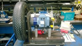
i have built the rig shown. it has a wheel and induction motor.

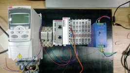
i have the drive and a plc and other peripherals on another panel see attached also.

i want to drive the motor with the drive through the PLC and a SCADA system. i then want to break the wheel and dissipate the energy over a resistor.

basically i want to be able to measure the speed of the wheel during acceleration and deceleration and be able to measure the regenerated power during deceleration. i have most of the SCADA and PLC side sorted out in that i can communicated and start the drive via the hardware inputs.

i need some way of setting up the motor to accelerate and then decelerate the wheel as quickly as possible, simulated a quick braking scenario and have some sort of analog signal that shows the regenerated power from the drive.

WP_20140106_013.jpg WP_20140107_001.jpg
 
Hello jraef, thanks for the reply
i have built the rig shown. it has a wheel and induction motor.

i have the drive and a plc and other peripherals on another panel see attached also.

i want to drive the motor with the drive through the PLC and a SCADA system. i then want to break the wheel and dissipate the energy over a resistor.

basically i want to be able to measure the speed of the wheel during acceleration and deceleration and be able to measure the regenerated power during deceleration. i have most of the SCADA and PLC side sorted out in that i can communicated and start the drive via the hardware inputs.

i need some way of setting up the motor to accelerate and then decelerate the wheel as quickly as possible, simulated a quick braking scenario and have some sort of analog signal that shows the regenerated power from the drive.
Right. So run a test and put the drive in regen, then observe parameter 0106 and see if it shows something other than 0 when braking (by the way, "breaking" the wheel would be like snapping it off, BRAKING is stopping). To get the fastest possible stop, set the drive to Decel in the shortest time frame possible, i.e. 0.1sec., the drive will then automatically engage the brake chopper and fire into the resistor when you remove the Run command.

As far as Accelerating as fast as possible, make sure you set up and enable the drive to run in Vector mode (9904 = Vector: Speed) and do an Autotune (2305 = 1) and set the maximum Torque to 600 (parameter 2017). The drive will not accelerate the load any faster than it is capable of, in other words it will override your settings to protect itself, so just be prepared for that.
 
when you say "put the drive in regen" do you man simply press the stop button? i mean if you are in local mode? would a very quick stopping time be realistic do you think? the accelerating time is not important, it can be 15 sec. however i would like a very quick stopping time

i did a test yesterday and tried to rotate the wheel with the drive in local mode. i have not carried out any parameterisation of the drive so far. unfortunately i only have a two pole motor and i found that i had to manually give the wheel a spin in order to get it driving.

my particular drive has dynamic braking and not full regen braking. can i use any standard power resistor for the braking resistor? i have noticed that abb specify their own special resistors in the resistor sizing section.

you mentioned that it may be difficult to measure the regenerated power. is it unrealistic to measure the voltage and current through the braking resistor?
If you have not done any drive programming yet, it's highly likely it would not accelerate your motor well. You need to do that.

Technically you can use your own power resistors, if you know the right size. If ABB gives you that, fine. If not, it can be risky.
 
ok i see thanks, i will try it tomorrow as i am testing a larger power 8 pole motor on the drive (as the 2 pole motor was not starting the wheel from standstill, however the vector control may resolve the issue with the 2 pole motor)

referring to the orignal schematic i posted in the first post, are you aware of how you would impliment an acceleration and braking operation using the harware digutal inputs? i.e. do you simply sent a 1 to DI1 to accelerate the motor and a 0 to DI1 to casue the braking?

ideally i want 3 input.

1. analog i/p to set speed
2. start command
3. braking command

however i would imagine that if you use the start command then the motor will automatically go to a predefined speed rather than to a speed set by the user?
You don't have to tell it to brake, read Highland Control's first post. It will do it automatically when you remove the Run command. I don't know what your Digital Inputs are programmed for, so it's meaningless to speculate. But if you are using basic 2-wire control (a single command to Run, removal of which is Stop), then if you set the Stop Mode programming to tell it not to "Coast", it will brake if and when it needs to. Then if you set the Decel time to 0.1 seconds, that means basically that it will always need to.
 

Similar Topics

Hello I have an ABB ACS350 drive and am having trouble with the run enable parameter. when i active the run enable command parameter "1601" i...
Replies
12
Views
6,042
Hello, I know this might not be the proper place to ask, but I googled the ACS350 and it led me to this site, so I thought what the hell I'll give...
Replies
10
Views
7,521
Hi All ! I am having a problem with a pressure/vfd controlled water irrigation system. The basic set-up is a danfoss 2 wire pressure tx 4-20mA...
Replies
4
Views
2,650
I would like to know will it be possible to read all the parameters of the ACS350 drive of ABB make through devicenet protocol, or is it limited...
Replies
5
Views
2,787
does anyone have an install or know if/where i can download it for the following "ABB PS501 Control Builder Plus V2.3 " the software was a free...
Replies
2
Views
87
Back
Top Bottom