Hello, new here nice forum. need experienced help

Join Date
Jan 2014
Location
evansville
Posts
12
I have a Micrologix 1000 running AC Power. I have a trainer from plc-trainer.net. It is all DC and wired for a Micrologix 1500. I have a DC SUpply for the components, and i can successfully power up my Micro 1000. I was using the Micro 1500. But ran into the issue of having to purchase Rslogix. I was advised to instead save money and purcahse a micro 1000 to use with rslogix free version. I am a beginner. very interested in programming and automation. to get started i really need help getting the MIcrologic 1000 AC to work with my DC components. anyone have any ideas? the trainer includes 4 lights, 4 switches, 1 power switch all pre wired for DC with DC common. I really do not want to hook anything up without proper instruction or guidance. I appreciate any help i can get. and i do apologize for the newbie questions. But im just a nerdy guy desperate to learn how PLC's interact with real world objects and get started on programming. That i'm sure i will excel at. Thank you and be gentle lol haha.
 
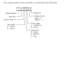
Can you provide the forum with the complete catalog number of your ML1000.

catalognumber.PNG
 
Last edited:
For inputs to your ML1000 you could use interposing relays controlled by 24VDC and then power the dry contacts of the relays with AC to connect to the PLC's AC inputs.

For outputs just use the ML1000 relays which can control both AC and or DC.
 
so i have absolutely no ability to use DC components with this unit? Even if powered seperately? IS ther any case i can use DC components at all with an AC unit and if so how could i do that in very simple example? I just need to know if i need to buy new components?


See my post (#5) above. You will have to buy some small relays though.
 
Because your Micrologix1100 has relay outputs, the voltage on the outputs does not matter. I would tie 24VDC+ to the "VACDC" labeled commons on the BOTTOM of your PLC and then use "OUT 0", "OUT 1", "OUT 2", "OUT 3" to your lights.

Because you have the 120V model of Micro1000, you can't use 24VDC as inputs. But since all your inputs are simple switches, it shouldn't be an issue to rewire the switches, as long as they are rated for 120V. Just take 120V hot wire to all the switches and the return switch leg back to "IN 1", "IN 2", "IN 3", "IN 4" on the top of your PLC. Take line neutral to "COM" labeled terminal on the TOP of your PLC. Please note this will only work for switches and devices with dry relay contacts. ALso, please label everything nicely so people will know its 120V and not 24V on the switches and change the wire color if applicable.
 
Last edited:
For inputs to your ML1000 you could use interposing relays controlled by 24VDC and then power the dry contacts of the relays with AC to connect to the PLC's AC inputs.

For outputs just use the ML1000 relays which can control both AC and or DC.

As far as Outputs, i need nothing? DO i need a Common or just the devices powered where they are. Or do i need relays there as well? Please let me know if im running off course.
 
Because your Micrologix1100 has relay outputs, the voltage on the outputs does not matter. I would tie 24VDC+ to the "VACDC" labeled commons on the BOTTOM of your PLC and then use "OUT 0", "OUT 1", "OUT 2", "OUT 3" to your lights.

Because you have the 120V model of Micro1000, you can't use 24VDC as inputs. But since all your inputs are simple switches, it shouldn't be an issue to rewire the switches, as long as they are rated for 120V. Just take 120V hot wire to all the switches and the return switch leg back to "IN 1", "IN 2", "IN 3", "IN 4" on the top of your PLC. Take line neutral to "COM" labeled terminal on the TOP of your PLC. Please note this will only work for switches and devices with dry relay contacts.

Wow, lot of knowledge. Thank you. A diagram would help very much so. All ican say out my devices is they are all 24VDC. They are definitely an off-brand. nothing standard. But yes a diagram would help.
 
ok is this how it would be done normally in real world? or would it be planned to be used DC to DC or AC or AC?

In the real world, you pick a PLC that goes along with what input voltages your devices are. If you have multiple voltages, you use multiple inputs cards. If you just have a few inputs that are the "wrong" voltage or are using a PLC that doesn't allow addon cards, you use physical relays.
 
The main thing im worried about is wiring something incorrectly and creating disaster. Since the devices are all DC and the Unit is AC. I didn't know how to tie the two together without disaster. Do the I/O wires even have power? and if so. how much? The reason i ask is because if those wires are attached to the PLC that is AC. wouldn't they have to be AC current? Or DC? Anyway i really appreciate the help so far. would really love to get this knocked out so i can really star toying with my PLC.
 

Similar Topics

hello, i am maggiesparky and have visited this forum many times and just love it. well i have a ladder diagram question and ask for your help to...
Replies
13
Views
3,848
Hello everybody just signed up to the forum and thought i'd say hello. I've been "guesting" on the site a bit over the past month and thought i'd...
Replies
7
Views
2,019
Plcs. I need to copy integer files from 5 different Plcs into one Plc. I'll be communicating thru the ethernet, and the Plc type is Allen-Bradley...
Replies
3
Views
1,910
Hi, I am new in PLC. I am taking the course this semester in my college. I need some help.Thx for your kindness for helping me first. I am...
Replies
9
Views
2,468
I have an HMI 2711R - T4T Series B, and I want to know which PLCs, besides Micro 820, can communicate with it.
Replies
2
Views
80
Back
Top Bottom