IA input on Micrologix 1100

Narlin

Lifetime Supporting Member
Join Date
Mar 2010
Location
phoenix
Posts
320
[FONT=&quot]I am using a 2nd voltage source putting out 10V calibrated to NIST and verified. When I apply it to the IA input & IA com on a Micrologix 1100, I only see .78 volts on the calibrated voltmeter and a similar and maybe correct very small reading on the Micrologic I:0.4 and/or I:0.5 depending on which 1 I connect to. Does this implicate a bad PLC IA or am I missing something?[/FONT]
[FONT=&quot] [/FONT]
[FONT=&quot]narlin[/FONT]
 
Your terminology makes it seem that something is wired wrong. There is no 'IA' input on the Micrologix 1100. There are, however, two 'IV' inputs.

Can you provide exact information on the voltage source, the calibrated voltmeter and exactly how you have them wired to the Micrologix?
 
It is IV1 & IV2. not IA.. Also the voltage source is 10V DC? The manual seems to say that these are 0-10V AC inputs - could that be the issue? I'll try to attach a picture on the next post.
 
Remember the warnings in the MicroLogix 1100 User Manual, specially the one about the analog voltage channels not being isolated from each other. Do you have something connected to the other channel?

Consider the following when wiring your analog channels:

The analog common (COM) is connected to earth ground inside the module. These terminals are not electrically isolated from the system. They are connected to chassis ground.


Analog channels are not isolated from each other.


Use Belden™ 8761, or equivalent, shielded wire.

Under normal conditions, the drain wire (shield) should be connected to the metal mounting panel (earth ground). Keep the shield connection to earth ground as short as possible.


To ensure optimum accuracy for voltage type inputs, limit overall cable impedance by keeping all analog cables as short as possible. Locate the I/O system as close to your voltage type sensors or actuators as possible.

(Bernie, I think there is a little "IA" printed above the "COM" terminal for some strange reason).
 
Last edited:
The MicroLogix 1100 analog inputs are made to sense 0-10 V DC, and have an input impedance of 210 K ohms. Your voltage source should have no trouble handling the tiny draw of the analog input, but clearly something is pulling down that input.

The MicroLogix analog inputs are 10 bit resolution, so 10 volts should result in 1023 "counts" in the I:4 or I:5 data register.

0.78V would give you a value of 79 or 80 in the Input register.

Go grab a small flashlight battery and try that as a voltage source.

Edit: if you have a manual that shows these as AC inputs, your manual has somehow been translated into Klingon. They are DC analog inputs.
 
Narlin,

if i understand your post correctly, you have a power source 10 volts connected to the current input of the plc and you are only reading .78 volts. this could be a correct reading

you are mixing voltage signals with current signals and they are totally different.

an analog input voltage measures voltage.
an analog current input measures current, reguardless of the voltage.

on the other hand,
if your power source is 10 volts and you are only reading .78 volts at the end of the wires (not connected to the analog input) i would look at voltage drop, type of cabling, wire size, consider 4-20 ma logic. also, is this a cable or wire?
if its a cable, is it shielded and grounded on one end only?

as Bernie said, post your details.

regards,
james
 
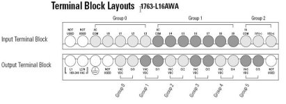
There may be some AC Inputs, as well as the two analog voltage inputs IV1 and IV2. Notice the "IA COM" confusion factor!

Micrologix 1100 1763-L16AWA Terminals.JPG
 
I hate, hate, hate the fact that MicroLogix relay common terminals are labeled "VAC VDC" instead of "RLY COM" but the "IA COM", grouped with the "IA1" and "IA2" termnals seems unambiguous.
 
I grabbed a 1.5 v battery and used it for the input. Immediately got 153 counts. Probably the M1100 is working. Thank you.

Still have the same issue though with the other source. 10V changes to .78V and gives 79 ro 80 counts. Again confirming the M1100. But my circuit has an issue?

1100 Instruction set reference manual Chapter 1, page 1-1 “Embeded I/O” says that these are 0 to 10V ac analog for all 3 versions BWA, AWA, and BBB. I have used these voltage inputs before, but only from current sources using 500 ohm resistor to convert to 0-10V. of course it was DC – head bang.

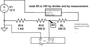
I am going to try to post my circuit as a bmp. We’ll see. Meanwhile, the purpose of this circuit is to use a resistive level transmitter that varies from 0 to 7920 ohms and then get a voltage signal from a voltage divider that varies from low to 10V (note linear with level on the 1/V).

quickpic.jpg
 
On the terminal labeling, I suppose that "1A" stands for "1 Analog", but I bet some old SLC 500 user has already assumed it meant "Amps" and has connected a current input to it.

The analog input internal resistance is 210 kOhms. Perhaps that is affecting your circuit.

Is the water level transmitter like a standard potentiometer and if so, do you have the center variable-voltage wiper of the water level transmitter hooked to your RL resistor? If the water level resistance stays at maximum 7920 Ohms, that would make your voltage at "R3" calculate to about 1.4 all the time.

Maybe the transmitter is not working or does not have enough output current for your load.
 
Last edited:
Neglecting the input impedence we have 1100 ohms across the input terminals. With the 210 K ohms added in parallel it gets reduced to 1094 ohms. Not much of a change.

But it does give 9.99 volts when the variable resistance is at zero.

The original post said you measured .78 volts but your diagram says you are measuring 10 volts. I'm confused.
 
Last edited:
[1100/(1100+220)]*12V = 10V by & by the voltmeter agrees.
That is for 0 resistance from the varible volage resistance. (it is out of the circuit).

More info. The 1.5V battery gives 153 counts. But a 9V battery (verified) falls fast in counts from about 900 to around 400 but still going down (over 3 seconds) and I won’t leave it connected long enough to fry whatever.


If the PLC is out of the circuit and i use only the Voltmeter and the Variable Level Resistor is out of the circuit, then voltmeter shows 10V at R3. If the PLC is connected instead of the Voltmeter, and as shown in the diagram, then the PLC reads 79 counts. If i leave the PLC connected and check the voltage at R3 vs GND, the voltage is 0.78. Yes it is an oxymoron. If this were easy i wouldn't be here.
 
battery: 1.5V gives 153 counts
battery 3.10V gives 245 counts (should have been 373 counts)
battery 9V stabilized at 509 counts (yes i held it long enough)
circuit 10V gives 79 counts

narlin
 

Similar Topics

Hello. I am unable to find information regarding the input mapping for the embedded inputs for the Micrologix 1100. as far as I can tell, inputs...
Replies
1
Views
1,612
Micrologix L16BWA It has two built in analog input ports. How do I change the input type and range? current/voltage, 0-5v, 0-10v, 4-20ma, etc...
Replies
6
Views
3,876
I am attempting to make a cleaner menu of the LCD display and I was wondering if there were raw input bits from the Keypad (Up, Down, Left, Right)...
Replies
1
Views
1,188
i have a pt100 4-20ma is the analog input on micrologix 1100 only for 0-10V ?? 🔨
Replies
4
Views
3,629
I am trying to put together a program for a control valve and scale combination. I will be using a ML1100 PLC, a 1762-IF4, and a 1762-OF4. I will...
Replies
8
Views
9,620
Back
Top Bottom