CLX RIO PLC5 Analog

Jordan546

Member
Join Date
Nov 2013
Location
Canada
Posts
49
I know there have been a couple different posts on this subject but I was still unable to get the final information needed.

In my facility we are in a progressive upgrade to CLX and rather than convert the whole system we are implimenting a CLX processor and IO for the local(main) chassis and keeping the existing RIO as RIO. I have a L63 Processor with a DH/RIO module, a few IO and an ethernet module in the main rack and my remote rack has a couple 1771-IFE and OFE2 and then a couple discreet IO.

I have assembled a test bench with the following configuration.

Main Rack:

PowerSupply
1756-L63
DH/RIO Module
e2nt ethernet module
a couple IO modules (unimportant)

Remote Rack:

1771-asb
power supply
1771-IFE
1771-OFE
1771-OAD

I currently have the DH/RIO module connected as RIO to the PLC-5 Rack and I am communicating and I can change the outputs on the discreet card. Now I am having troubles with the Analogs both in and out. I know that a message is required to replace the BTR and BTW of Logix5 and I thought I had it all set up but unfortunately it does not seem to work as the messages go into Error.

Once I get the messages figured out I can do the actual plant implimentation myself no problem as it is just altering some of the numbers to meet the exact configuration. I can send you the ACD file but I am unable to attach it here for some reason.

Any help would be greatly appreciated.
 
I can send you the ACD file but I am unable to attach it here for some reason.

you'll have to ZIP the file before you can post it (forum rule) ...

it would also be VERY helpful if you could also post the original RSP file for the PLC-5 system ...

secret handshake: the older RSLogix5 software was able to generate the "configuration data" necessary for the analog input and output modules to work ... the newer RSLogix5000 software doesn't have that same capability ...

so ...

you need to set up arrays of INTs (specifically NOT the default of DINTs) and use the Block Transfer Message instructions to work with those arrays ...

plus ...

you need to MANUALLY populate the BTW configuration INTs with the proper values to get the analog modules to work ... the easiest way to acquire the proper values is by examining the data from the previous RSP file ...

also – on the "digital" side of things ...

make SURE that your maintenance crews are FULLY aware of how the ControlLogix system is going to address the bits associated with your digital input and output modules ... specifically, the PLC-5 used OCTAL addressing – and the LEDs on the modules were numbered accordingly ... (zero through seventeen – with no eights or nines) ...

but ...

the ControlLogix system is going to number those same bits using DECIMAL addressing instead ... (zero through 15 – WITH eights and nines) ...

potential problem:

at three o'clock in the morning it is entirely too easy to be troubleshooting a bit numbered "15" in the ControlLogix taglisting – and not realize that the corresponding LED (and terminal screw) on the front of the module is actually labeled as number "17" ... GOTCHA! ...

also ... this next isn't usually a problem with "normal" systems – but can be disastrous with systems that rely on "high speed" I/O signals ...

when the PLC-5 processor was located in the same chassis with the I/O modules there was little or no "delay" in communications over the chassis backplane ...

but ...

suppose that the PLC-5 processor has been replaced with a 1771-ASB Remote I/O Adapter – and the other end of the blue hose cable is now attached to a 1756-DHRIO module ... the extra hardware creates something of a communications "bottleneck" that didn't exist before ...

so ...

sometimes when the "old slow" PLC-5 processor is replaced with a "new fast" ControlLogix processor, the system won't work ... the reason might be caused by that communications bottleneck that I've just described ... this might not be (in fact, it probably won't be) a factor with your system – but it's something that you need to be aware of - if I/O signals are being intermittently "missed" or "skipped" by your "fast new" ControlLogix processor ...

finally, the DHRIO module is usually VERY picky about having the proper terminating resistors installed on the blue hose cable ... if you don't have those correctly installed, you should start there ...

good luck with your project ...
 
Last edited:
Ron,

Thank-you for the reply. I believe that I have set up the array of data as I should and I did in fact use INT and not DINT and I configured it in the older version of PLC5 using the configuration words. I also cross referenced that with the manual to try and see what was happening and make sure it was correct.

I think that my acd file is attached and the RSP doesn't really apply because the cards and configuration etc have all changed. I can make a new one and attach that if it is still neccessary.
 
I have set up the array of data as I should ... and I configured it in the older version of PLC5 using the configuration words.

double-check that part ...

I'll be traveling – so offline for the rest of the day ... no time to look at any of the other items ... good luck with it ...

.

ife_no_data.PNG
 
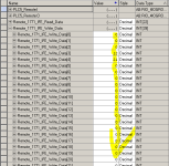
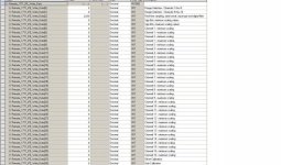
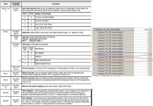
Thanks I did change that now. I have attached the configuration I used. This still does not work. The write gives me an ER and it seems as though the read doesn't ever give me a power up bit.

Data Block.jpg config.jpg
 
What is the ERR code you are getting in the MSG instruction?
FYI - The BTW to the IFE only has to occur once to configure the module, then you just need to read.
I would get the MSG working first (Get a DN bit), then worry about the configuration of the write data.
 
I do know it only needs to write once and then it will be configured and does not require additional scans. Here is the ER I get.
 
Last edited:
Show us your I/O configuration....Have you defined 'RIO'? The Message instruction is complaining that the RIO path is non-existent.
 
Is the communication to the remote rack working (Active LED on ASB)?
Is the slot location for the IFE / OFE correct?
 
also check (and double-check) the DIP switches on the chassis backplane ... these must be set DIFFERENT when changing from a PLC-5 processor over to a Remote I/O Adapter ...

and be sure to use the manual for the Remote I/O Adapter - not the one for the processor ... the assignments of the DIP switches aren't even the same from one device to the other ...
 
Sorry I don't have access to the system saturday-tuesday. The remote IO is configured correctly as I can communicate with the discreet IO. All the LED are on that are supposed to be on and all dipswitches are good. The only issue is getting these analogs to work. I have written the message as best as I can tell to be correct and the control logic is basically a direct copy of the PLC5 logic.
 
I guess I should mention I am only using RSlogix5000 Rev 16. I do not currently have a tech connect contract to update to 20. I am unable to go to studio as I do not have a windows 7 computer at this time.
 
make SURE that your maintenance crews are FULLY aware of how the ControlLogix system is going to address the bits associated with your digital input and output modules

I am one of the maintenance guys of the shop and the three of us are the ones that will do any PLC troubleshooting. Thanks for the heads up and concern though
 

Similar Topics

Can i terminate(put resistor in terminal of channel a)the blue hose of an existing plc5 dh+ network to a new 1756-dhrio in new clx rack without...
Replies
8
Views
2,720
Curious if this is possible. I am working on a PLC5 to CLX conversion. Due to panel space limitations and time I need to replace a small PLC5...
Replies
4
Views
3,495
Hey fellas, I did a search but didn't find anything that quite fit. I'm setting up a new CLX chassis (with processor) for a new project. I need...
Replies
5
Views
5,524
I am trying to send some datas from PLC-5 to control logix plc through 1756-DHRIO. When I go online to PLC-5, Message instruction gives error &...
Replies
15
Views
3,348
Upgraded a PLC-5/80 today to a CLX. There are 5 physical ASB modules for a total of 10 racks. All 10 are added in the CLX tree under the DHRIO...
Replies
14
Views
4,376
Back
Top Bottom