Wiring HART Transmitter through Conditioner

shawnhimself

Member
Join Date
Oct 2006
Location
LBC
Posts
84
I have a project that is requiring the use of signal conditioners with all 4-20mA transmitters and I am a bit confused on the wiring.

I have attached a quick sketch of how I THINK it should be done, but wanted to get a second opinion on it. Also attached are the data sheets for the 1756-IF8H analog input card and the AB Signal Conditioner.

Any input is appreciated 🍺
 
Whoa! Isolator terminals 2 and 1 are swapped. 2 goes to transmitter negative, 1 goes to transmitter positive.

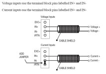
I'm not sure you need any connection to RTN because the example you show, figure 6, is for loop powered transmitters that share a single power supply. Although your transmitters are loop powered and likely share the same power supply, the output that the AI card 'sees' is from the Isolator, which makes the makes the current signal look like an active 4 wire current input to the AI card. I suspect that connecting to RTN might force your differential card into single ended performance.

If it were me, I'd try it without any connection to RTN and see how it works. Each channel still needs its INx(-) connected to RTN-x.

It's important that you use a HART isolator, like you've picked, because isolators that are not HART isolators will strip off the HART signal, leaving just the 4-20mA.
 
Oops, yes the sketch should have the terminals swapped.

I will try it without wiring into the RTN initially and see how that works out, easy enough to add after the fact. Thanks for the insight.
 
The only connection 24Vdc(-) should have is to the isolator module.

You want to jumper INx(-) to RTNx, not connect RTNx to 24Vdc(-).

Avoid connections to 24Vdc(-)

The purpose of using an isolator is to isolate the field device from the analog input card. Making lots of connections to a point that is both common to the field device and to the AI card voids the concept of isolation.

The spec sheet for the 931h isolator, under Input Ratings, states "supply voltage of 16.5V / constant for 3-22mA". I'm assuming that since it is a HART isolator that the isolator provides sufficient voltage to run a loop powered HART transmitter throughout its full current range.

So powering the loop transmitter separately shouldn't be necessary, as osmanmomin proposes. All those connections to 0V eliminate the isolation that the isolator is supposed to provide.
 
osmanmomin:

Like danw said, the HART isolator is active (powers the loop), and if you also want to Isolate the sensor from the control panel, why do you want to use another power supply to power the loop?
 
See revised drawing...

I'm assuming you're saying to power only the isolator (as it is an active isolator) then have the transmitter run through that, to the card, with IN0- and iRTN0 jumpered.
 
See revised drawing...

I'm assuming you're saying to power only the isolator (as it is an active isolator) then have the transmitter run through that, to the card, with IN0- and iRTN0 jumpered.

I agree with this diagram. I will not comment on the IN0- and iRTN0 because I use Siemens PLC's.

In this diagram, the sensor is 100% isolated from the control panel.
 
Polarities are reversed in the latest drawing, (except for power supply to isolator, which is correct).

Should be negative to negative, positive to positive.

Txmtr(+) is miswired to isolator input (-) (terminal 2)
Txmtr(-) is miswired to isolator input (+) (terminal 1)

Isolator output (-), terminal 5, is miswired to AI (+)
Isolator output (+), terminal 6, is miswired to AI (-)

It is correct in removing the power supply from everything but the isolator.
 

Similar Topics

Hi guys, I am about to purchase a Hart to modbus converter to interrogate a few flow meters on hart and get the info via modbus. All looks good...
Replies
2
Views
2,109
Posted this to Reddit with little success, so I figured I would share it here as well. Very new to PLCs, but figured I would give it a shot to...
Replies
0
Views
122
Hello Folks, Has anyone configured a Momentum high speed counter on Unity 13.1. We need the wiring diagram for Momentum High speed counter and...
Replies
0
Views
76
Hey guys, the scenario is: I have already completed the drawing package for my system utilizing an A-B 440R-N23126 (Minotaur) safety relay. SoS...
Replies
0
Views
136
Maybe a stretch to call this a PLC question, but it does connect to a PLC input. I have two German switches: Sick WL9LG-3P2232 And a...
Replies
0
Views
109
Back
Top Bottom