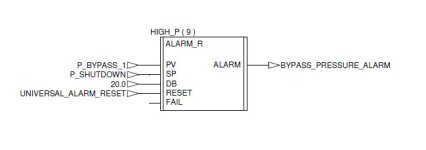
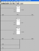
Please explain this Modicon Code.

jgreg07

Member
Join Date
Jan 2014
Location
Alexandria, VA
Posts
4
I don't understand why this code is written the way it is. It is from a Modicon Quantum. It is in a custom function block. The calling block is first: Thanks for any help.

I will try to attach the images. First attempt failed.

Alarm.jpg Refined Alarm Block .jpg
 
Alarm is raised when process value is bigger than setpoint. Alarm can acknowledged, but alarm goes off only after, when process value drops below setpoint - hysteresis? This however won't work that way ;)

p.s There is maybe typing error inside of block, reset swicth should be on network line 2. after alarm holding, instead of line1 before alarm coil?

SetReset flipflop is made for some reason also without built in functions.
 
Last edited:
I am guessing. I haven’t worked with Modicon since 1994 but will give it a shot. I described each line using the picture but the pictures did not paste into this reply but you will get the idea. Best thing to do is quit this place because they use MODICON and go find a job that uses RSLogix or Step7.

In these pictures, the Math Functions are always Enabled so they calculate (update) every scan.


If the Process Variable falls out of Range of the Setpoint by 20 (deadband) then ALARM BYPASS_PRESSURE_ALARM and set the FAIL Bit. The FAIL bit is in the ALARM ladder logic on second picture.

If your Process Variable = Setpoint Then COMP1 is True.


If you are NOT in Alarm and COMP1 is True then INTER is TRUE.


The Setpoint – Deadband = DIFF (a calculated value from the subtract block)


If the Process Variable Value drops below the DIFF Value then COMP2 is TRUE


INTER is True so if COMP2 goes True then ALARM. ALARM latches itself in and is Reset by the RESET Button. FAIL also sets ALARM true.
 
I don't get it. In order to latch the alarm bit on both of the compares must be true. However, if PV is greater than SP then it is by implication greater than SP-DB unless DB is negative. If DB is negative both compares will never be true at the same time.
In the end the alarm will latch up any time PV>=SP assumng a positive DB.

Keith
 
The alarm is only raised once Pv > sp-db and PV >=sp
DB just for an offset if needed i guess.
To me the reset looks fine. Alarm will latch until it is reset
 
p.s There is maybe typing error inside of block, reset swicth should be on network line 2. after alarm holding, instead of line1 before alarm coil?
I agree we Lare the Reset should be on the line after the Alarm interlock, that way even if the reset input is on the alarm will come up (a reset should only reset an alarm not prevent it from coming on)

Chuds assessment of the operation is correct

ps this code would be much clearer if written in FB not ladder, also if someone takes the time to build a DFB they should put a comment in it to describe its operation
 
I agree that chud's assessment is correct. But does that really make any reasonable sense? If PV >= SP then PV MUST BE >(SP-db) if db is positive. This makes the PV>(SP-db) comparison useless.

My guess would be they were looking for a delay element in there but didn't get it.

Keith
 

Similar Topics

Just for readers in the US, when I write 'gas' I mean it as a state of matter, not shorthand for gasoline :-) I don't understand the logic of a...
Replies
39
Views
11,170
Good Morning , Could you please explain to me what a S:FS is , what the purpose of it is and why would it be used in a rung. Thanks so much.
Replies
4
Views
1,716
Good Afternoon , We have a number of Kinetix 6000 Servo Drives and motors. I'm trying to understand these a little ( really alot ) better...
Replies
16
Views
6,339
Good Afternoon , We have a new machine from Italy , and for some reason , the servo actual positions quit updating on the HMI. I looked at...
Replies
6
Views
1,713
Hello, I started my new job at a factory and I found that when I opened the PLC cabinet there are "ABB contactors" that are connected to the PLC...
Replies
9
Views
3,325
Back
Top Bottom