PWM Sweeping sound output effect for alarm

mitureg

Member
Join Date
May 2013
Location
Canada
Posts
199
Hello all, thank you for reading this post.

I have this project where we need to created a sweeping sound alarm in TwidoSuite for a fire alarm on a boat.

So far we were able to alternate between 2 frequency, but we are looking a sweeping (or sliding) sound frequency.

Any ideeas on how to program that in TwidoSuite with the PWM function blocks?
I heard of Duty Cycles in Logix, would there be any equivalent in Twido?

Much appreciated,
Alex

EDIT: Any examples, explanations/guidelines in Logix would be also greatly appreciated.
 
Last edited:
I have never tried to generate a varying sound with a PLC. Normally most of us are happy with the standard external horns, bells, and sirens that can be attached to a PLC output. However, if you just have to try it, it appears that the Twido PLS function block might be the best to use. You can set a Preset Period and make that Period adjustable mid-period by setting the "Adjustable" box to "Y". Then you can use an Animation Table to vary the frequency of your output as the tone progresses. I think a place to start would be to find a graph of your desired sound, a Frequency versus Time plot. Then you might be able to figure out how to set up an Animation Table to duplicate that sound. It will require a lot of trials and testing to get the sound that you want, so this will take some time to work out. Without the same setup and horn output, it will be hard for anyone to help you with this.
 
Hi Lancie, I was able to get something decent today. So far we tried having S4 bits alternating 2 frequency with a %PWM box.

I finally got the sweeping sound using the value of a timer TM0.V in conjonction with the Pulse Width Modulator. The 10ms setup with a 20 second timer seems to work well. We do not hear each notes. It's sounds like a laser gun.

Usually I think a sequence will be organized for a fire alarm, going from a selection of 3-4 sounds. One dissonant buzzer, an alternating one and a sweeping one.

Will keep you updated,
Cheers.

Alex
 
I would like to see your program, if you could print it to a PDF file and post here.

One big headache with the TwidoSuite software is that you must select the PLC to be used as the first step before you write the program. If you later see that you could get by with a cheaper Schneider model, too bad, because when you change to a different PLC within the same program, your old program for the previous model is wiped out! The software always starts in default mode with one of the largest, most complex, most expensivie modular Twidos (TWDLMDA40DTK) automatically selected. Schneider must think that making that the default PLC will sell more expensive models, but it tells me to avoid this monstrosity software like the plague.

Maybe there is a way to start a new program for a new Twido model PLC, then import the old program, but it seems to be a flaw in the software, because most other brands allow changing PLC models at any time while retaining the old program.
 
Last edited:
Sure I will post a PDF. Yup I haven't found a way to import a project in a new hardware config. I got in the same situation at first when we had to change config, I lost all my I/O's.

TwidoSuite seems like a cheap bundle-wrap software put up together in order to make a buck over the research made by several competitor Sneider acquired over the years.
 
I have never tried to generate a varying sound with a PLC. Normally most of us are happy with the standard external horns, bells, and sirens that can be attached to a PLC output. However, if you just have to try it, it appears that the Twido PLS function block might be the best to use. You can set a Preset Period and make that Period adjustable mid-period by setting the "Adjustable" box to "Y". Then you can use an Animation Table to vary the frequency of your output as the tone progresses. I think a place to start would be to find a graph of your desired sound, a Frequency versus Time plot. Then you might be able to figure out how to set up an Animation Table to duplicate that sound. It will require a lot of trials and testing to get the sound that you want, so this will take some time to work out. Without the same setup and horn output, it will be hard for anyone to help you with this.

I recall, maybe a couple of years ago, around Christmas, one of our members posted a video of a PLC he'd programmed to play "Jingle Bells".
 
Hi,

Be advised that fire alarm systems normally have a controlling authority that defines all sounds (timing/tone/frequency/order), flashing, resetting, suppression, etc.. Ships/boats normally are covered by several overlapping authorities.
 
Last edited:
Alright I got a sequence for 3 different tones. They are an alternating tone, a sweeping tone (like a lazer) and an interrupting tone.

I didn't take any consideration for regulation with regards to frequency, tones etc.

I can seems to have the cascading timer working so far in twidosuite for an alternating state in a loop. The best I could find was a bit system, but I hate to rely on these tricks to make it work. Plus it's not very flexible.

I use the bit system for the alternating sound and the interrupting sound.

Have a look in attachment.
 
I can [can't ?] seem to have the cascading timer working so far in Twidosuite for an alternating state in a loop. The best I could find was a bit system, but I hate to rely on these tricks to make it work. Plus it's not very flexible.
Your comment is not very clear.

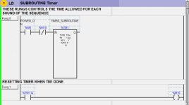
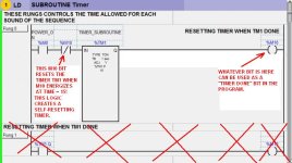
If you mean that you cannot easily get Timer TM1 to reset at the end of 15 seconds, then all you need to do is this: Connect the %M10 Relay on the right side of TM1.Q. Then when %M10 goes ON, the Normally Closed %M10 on the left side of Timer TM1 will cause TM1 to reset itself (become self-resetting. Then you can delete the entire Rung 4 (no longer needed).

Why are you putting your PWM activation inside of subroutines? For that matter, in this short program, why are you complicating it by using subroutines at all? You don't need subroutines, only correct logic to make this work.
 
Hi Lancie, I meant "I can't seems to have the cascading timer working..." you assumed well.

Lancie1 said:
If you mean that you cannot easily get Timer TM1 to reset at the end of 15 seconds, then all you need to do is this: Connect the %M10 Relay on the right side of TM1.Q. Then when %M10 goes ON, the Normally Closed %M10 on the left side of Timer TM1 will cause TM1 to reset itself (become self-resetting. Then you can delete the entire Rung 4 (no longer needed).

So you mean creating a new rung alltogether with TM1.Q as an input and %M10 as a output coil on the right side? Because now as it is, I am not using the TM1.Q bit anywhere. If I delete rung 4, it will also delete %M10. I think I misinterpret your indications. Could you rephrase it or paste a rung?

Lancie1 said:
Why are you putting your PWM activation inside of subroutines? For that matter, in this short program, why are you complicating it by using subroutines at all? You don't need subroutines, only correct logic to make this work.

Thank you for your concern. I intended to do an exercise for subroutine in TwidoSuite. They seemed to be behaving different from Logix.

Also, I wanted to isolate the %PWM module by opening the contacts using subroutines because I had multiple signal at the same time causing unwanted sounds on the main program page. But that might have been a logic problem in my program. I will test it again later.

Much appreciated.
 
Read and look at the attached picture: Connect the %M10 Relay on the right side of TM1.Q. Then when %M10 goes ON, the Normally Closed %M10 on the left side of Timer TM1 will cause TM1 to reset itself (become self-resetting. Then you can delete the entire Rung 4 (no longer needed).

Also, I wanted to isolate the %PWM module by opening the contacts using subroutines because I had multiple signal at the same time causing unwanted sounds on the main program page. But that might have been a logic problem in my program. I will test it again later.
If you out the %PWM module inside a subroutine, then it will only be active when that subroutine is called (active). If you split part of a logic routine into two or more subroutines, then some will be active and others will not be active, making your logic faulty. All parts of logic needed to activate an output should be insdie the subroutine. If you put parts into another subroutine (as it appears you have done), then the parts cannot operate as a whole unit, making the program not work correctly.

Your PWm function block is INSIDE Subroutine 1. Therefore it is active for Sound 1. But then for Sounds 2 and 3 in Subroutines 2 and 3, the PWM will be inactive and will not operate. If you want to use the PMW for all 3, move PWM to your main "SUBROUTINE Timer". You should not have more than ONE copy of %PWM0. Use that in your main SUBROUTINE Timer, but change the Period and Rate parameters inside your other subroutines.

If you need logic that operates in sequence to create sequential sounds, use Step Relays, turning them ON in order. Use these Steps to activate the PWM module with 3 parallel trigger branches, with a Step Relay contacts 1, 2, 3 each on a parallel input branch to the PWM module.

TimerReset_TM1_Q.jpg
 
Last edited:
Hi Lancie, thank you for the correction on my last version. I did the modifications for the main timer reset, the PWM only used one time outside the subroutine, with parralel branches corresponding to each input type I want to apply on it at a given time in the sequence.

Furthermore, I wanted to reset all bits the first time ONLY the %M0 power ON is activated, but I failed to find a logical way to do this. Anything I try keeps reseting all bit at every scan.

The reason I wanted to do this is that a bit can stay on from a previous sequence that was interrupted, causing the alarm to start at a different point the second time it is activated.

New version in attachement
Much appreciated.,
Alex
 
Last edited:
I recall, maybe a couple of years ago, around Christmas, one of our members posted a video of a PLC he'd programmed to play "Jingle Bells".

Any links for some advanced PWM sound generation using ladder programming would be greatly appreciated for reference.

Cheers,
Alex
 
The reason I wanted to do this is that a bit can stay on from a previous sequence that was interrupted, causing the alarm to start at a different point the second time it is activated.
That would be very easy if you did not have to use the HMI toggle-type button (which holds your horn functions ON until reset). If I had the program I think I could add a rung to reset it one time anyway. Basically, each time a new horn button goes ON, it must immediately reset all OTHER buttons that might still be on. So the first function to be done for any one button is to reset all other buttons (except itself). So you would start the rung with the horn button, then a one-shot rising edge instruction, then parallel branches, each with one of the horn button addresses. You would need such a rung for ALL horn buttons, so that any one will reset all the others except itself.

If you would post the entire program, I could edit it to add the above rungs.
 

Similar Topics

Good morning! I'm trying to find a DIN rail-mountable 4-0channel PWM amplifier that is capable of accepting a 5VDC PWM with a maximum frequency...
Replies
2
Views
105
I have a project to control the speed of motor DC using PWM Output on PLC and when im on working i have a several trouble and of of them is the...
Replies
6
Views
195
Hi All, I came up with this for ramping the PWM pin on the micro 820. I'm new to ladder logic so I am not sure if this will even work? Once...
Replies
6
Views
344
Hi, I am trying to have my PLC start a heating fan in a linear manner. A certain percentage at a certain received setpoint. To do this, I use a...
Replies
8
Views
1,578
Hi guys, i have never had to do a PWM Output or input before i have a Device that to dimm the lamp output from the ballast, the ballast has a 24V...
Replies
6
Views
1,022
Back
Top Bottom