Ladder style schematic

dmyers4

Member
Join Date
Mar 2014
Location
Mukilteo
Posts
6
Does anyone have experience drawing ladder style schematics?

I've got a prox sensor that has a cable which plugs into multi-box, which then has a combined cable that travels back to a cabinet and goes into some PLC ports.

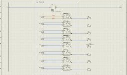
Here is how it was drawn originally. I'd like to convert it to ladder style, but it seems like it would kinda look terrible and be hard to follow.

ladder.jpg
 
So how is the result?
you are only missing the internal wiring of the multibox. rest looks fine.
If you are used to have +24V on left side have the sensors in the middle together with their plc connections.
 
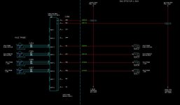
I just attached what I ended up doing. It does not show the internal wiring of the multi-box because it's split up into a bunch of different symbols so that I can move them across pages if needed.

ladder2.jpg
 
I'd like to convert it to ladder style, but it seems like it would kinda look terrible and be hard to follow.
There are two types of electrical drawing that are confused: Schematics, and connections. Ladder-style drawings are schematics that show the logical working of a device, but very little about the physical layout or physical wires. To show the physical side, connection wiring diagrams get complicated and involved. I know of no good way to convert ALL the information on a connection-type drawing into a schematic drawing.
 
Thanks Lancie. I'm working with my company to move away from the connection-type of drawing, which is great for building the product, to schematics, which are great for de-bug, and are the type of documentation our customers want.

So I'm trying to preserve as much of the physical nature stuff as I can, and when build notes are needed, I'm having people put them on a DO NOT PRINT layer.

Using SolidWorks Electrical for this.
 
I believe Lancie is on the right track. The different drawings have different purposes and you run into problems trying to condense all that information. I am assuming you are using cordsets with your devices. I do this a lot for the equipment I currently work on.

On the ladder diagram I show the from left to right a 24V connection, the proximity switch, and the signal terminated to the PLC. Additionally, I bring the 0V out of the bottom of the symbol and route that toward the bottom of the drawing to connect at 0V on the right. If there is an m12 or other QD that would cause a wire number/color change I indicate that here and provide a port number if there is one. I do not worry about showing the distribution box here because for the purposes of this drawing I don't think that is important and clutters the drawing.

I then have a connection drawing that is focused more on the physical layer. This is where I focus on showing the proximity switches connect to the cordsets and then to the distribution boxes. If the cordsets/cables are numbered I indicate that here. Because this drawing is focused more on the physical layer I use the 2d models supplied by the manufacturers for this drawing to show what they look like in the real world. I don't show the internal wiring of the distribution box because I have found it conveys little additional usable information, clutters the drawing some, and confuses the maintenance guys.

Finally I make a detail drawing of how to assemble the cables. I specify component/cable part numbers, assembly, terminations, and cable lengths here.

Long story short I break this out into three parts.

1. "Theory" - on the ladder diagram show how things are logically connected. Specify wire numbers and terminal numbers here.

2. "Connection" - show how the major components are connected on a connection diagram. Show the component, cordset, distribution block, and termination points. Label/number all of the aforementioned and specify a drawing for the cordset if necessary. Show the QD fittings here and precisely where on the distribution block they terminate.

3. "Physical" - show exactly how to assemble your cordset. Again, specify part numbers, cut lengths, and terminal numbers here for the cordset.

I have seen fewer errors during machine integration since I have broken the information down this way. It seems the crew I work with gets a little bit of information overload. This is my method and I would appreciate any feedback. Sorry about not having pictures handy.
 
I think your method sounds like it could work well. What program are you using to draw it to make sure all 3 drawing sets stay up to date? Like you change where a couple wires plug into on the theory page, does that then update in the connection page?

I think that's been a big motivator in the past for my company to stick with doing one drawing set. That and it's extra work to make more than one.

The EEs at our company are very project based. I do all of the schematics, buy all of the parts, assemble and wire the thing I'm building myself, or with help from an intern or tech. Most things we only build one or two of. This has in the past meant schematics didn't have to be very good because you know what you're doing. We're expanding and starting to do more and more repeats, so good documentation is becoming necessary.
 
I am in a very similar situation. My company designs and builds all of the equipment it uses for production. I have two electricians that do nothing but build and integrate and I do all the design, ordering, programming and commissioning. I understand your timetable. I have learned I don't have an excuse for shortcut ting on drawings. Somebody is eventually going to have to work on this stuff and I don't want to be in the position of not having a clear drawing to read 5 years ago. It would be embarrassing to cuss the engineer who did the drawing then see your initials in the drawn by box.

I currently use autocad lt 2013 so there is nothing special that auto numbers my drawings.

Manual changes using this method are still quick and easy in my opinion. For example if you changed the port you connected a proximity switch you would merely draw the connection from the switch to a different port. You then change the wire color/number on the ladder to reflect the port change. If you were changing Plc inputs you would cut and past your sensor to the new input.

The physical drawings almost never change assuming you use the same sensors or distribution boxes or the termination points are the same at least.

I will post some examples in a few moments.
 
Awesome thanks. What happens at our company is you are told build X. Look at how it was done for Y, using its schematics as a base, and then modify. When there are two or 3 places the same data is shown, just in different ways, only one of them ends up getting updated. I'm hoping to come up with a good solution using Solidworks Electrical.

I'm 90% there, but it does not handle cables very nicely, when you draw them in a one line diagram. It can auto-generate this really cool connection tables, which I am planning on customizing per component. They show what it connects to, what wire number was used, and all of the terminal numbers, based on how you drew them in the schematic.

So far, I've been able to incorporate enough of that in the schematic to not need the second drawing set.
 
I still like the first drawing, as it has more built info, when i am searching for something i like to know what unit it is, the internal wiring of this connection box is very simple.
I make a connection diagram with all terminals and cables on it.
a placement drawing where everything is (it has all numbers of units and their placement in the cabinet.
when a tag of a relais is missing they can make a new one from this drawing.
a schematic drawing with I/O to PLC , so when i operate a switch wich light should go on
a working diagram (what does it do, and how)
a sequence diagram (what happens) (SFC)
a settings diagram (all of the timers/counters and analog positions, example a pressure switch setting and a indication like press > 6.3 BAR = contact closes , meaning normal operation the contact is open)
a software diagram (an overview of the software blocks (CFC)
a simulation diagram on the visualisation to check all I/O
a list of manuals of subsystems (and i include them in the project map)
all of the software goes in the map, when they like to copy the machine, (it will give problems when installing, and i will double my fee, for repair)
as my installations are unreachable at sea i always give also the programming software to be able to help them from a distance.
 
I like your detail shooter. Unfortunately, I don't have the time resources I would need to generate all of that with my current software package . I would love to though. I think it would help a lot of maintenance guys and my electricians. That is assuming the read the material instead of just calling and asking me.

Here are some stripped down examples of the three drawings I was referring to. These are in addition to your physical layout drawings. They are from different drawing sets and aren't intended to correlate.
 
Ya, Cali, we do some drawings like your connection example. Ethernet cable layout, and other communication cables work especially well here for us.

Holy **** Shooter, that's a lot of different documents. But at our company we have electrical engineers who make the schematics, and controls engineers who actually program and run the machine. They maintain their own documentation, which probably includes a lot of what you have.
 

Similar Topics

Hello! I have a network of conveyors bringing raw product to 4 machines. A sensor in the hopper of each machine calls for more product. I'm...
Replies
15
Views
5,869
Hello, I am trying to replicate a piece of logic on the PLC5 onto an SEL RTAC. I am using ladder on SEL and FBD. I am having issue on the ladder...
Replies
9
Views
109
Hi all. Is this the simplest way to debounce inputs in Ladder (there are 2 points being debounced here)? The TOF drives the tag. I'm expecting...
Replies
15
Views
487
I have a machine which is undergoing upgradation. As part of the process two SEW drives are being replaced., existing Gen B with new Gen C. The...
Replies
3
Views
195
Does anyone have RSLogix 5000 ladder diagram program of tank leveling (factory IO). Fill valve, discharge valve, set point, level, etc? I looked...
Replies
2
Views
156
Back
Top Bottom