Optocouplers & Solid state Relays

Questor22

Member
Join Date
Mar 2014
Location
Ontario
Posts
7
Hello,
I have been reading online about optocouplers and solid state relays; I think I seem to have some misconception about their functions.
From what I know optocouplers are used to protect the internal circuitry of a plc what I am not sure about do they Step up and Step down the voltages ? if that is the case then would a motor be connected to an Optocoupler first before being connected to a PLC so as to prevent any reverse current from damaging the outputs ?.
Also would Solid state relays be able to control larger voltages say ( inputs for a PLC ) with a smaller control signal ? Please correct me if I am wrong.

Regards..
 
Hii Questor22 !!

In PLC applications Opto-couplers are widely used.
You are partly right that Opto couplers provide protection to Internal circuits from external circuits as they completely isolate the two circuits.The internal & external circuits are not electrically connected.It consists of a LED which provides a signal to a Photo-transistors which ultimately makes a switching.
They also do provide protection against High Voltages coming from external Circuits or generated from PLC dues to some disturbance by means of FUSE.
But they do not Step-up or Step-down the voltages.
Optocouplers simply provide Potential free contacts or Potential contact(usually 24 V DC) which are then tapped to Motor's Control circuit in the following ways:
1.In case of DOL & Start-Delta starter, the optocoupler provides a single contact to the Motor Circuit Contactor
2.In case of Circuit Breaker/Softstarter/Drive, the opto couplers provides 2 contacts viz. 1 contact to Breaker Tripping Coil and other to Breaker's Closing Coil


I hope this clears your doubts !!

Regards.
 
Correct me if I am wrong, so for instance say we have an Arduino 5V and a PLC 24V DC an optocoupler can be used to have the output of the PLC connected directly to the input of the arudino ALTHOUGH of the different voltages and thats because of the pullup resistor and the diode in the internal design. now my question is say I want to control the PLC input ( high or low ) through an Arduino output, don't I need a Solid state relay to do that and not an optocoupler ?

Regards..
 
hi questor,

Now tell me what is the configuration for PLC Digital Input Card ?
Means what is the Voltage Type of your PLC DI card...is it 24 V DC, 230 V AC,5 V DC or tell me the range of Voltges your PLC DI card can accept.
Also tell me what is the Output Voltage/range of voltages from your Arduino Digital Output Pin ??
 
PLC DI card is 24 V DC and for the output voltage range from the arduino digital output is anywhere from 0-5 Volts and I think if is is less than 2.5 it is not a HIGH
 
Ok so i understand that your PLC card accepts upto 24V DC and your Arduino generates an output of 0-5V DC.
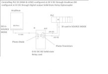
So here you are suppose to use an optocoupler(relay card) of 5 V DC the INPUT of which will be connected to the output PIN of Arduino.The output of the optocoupler will be connected with PLC DI card.

Please find the drawing giving a clear idea of the same.

untitled.jpg
 
Last edited:
Questor,

I have read your questions & clarifications a couple of times and am still not clear on what you are trying to do.

I'll start with some basics, which meghesh also explained. Optocouplers are used to electrically isolate a signal source from the circuitry of the device (possibly a PLC) that is receiving the signal. Isolation is necessary if the source and target are not referenced to the same ground, if the source is an AC signal, or if the source voltage is higher than the target can accept.

The way an optocoupler works is that it, internally, has an LED that will light when there is a signal on the input. It also has a circuit (commonly a phototransistor) that will turn on when the light is sensed. There is no electrical connection between the input and the output of an optocoupler. The only connection between the two is light.

Before weighing in on just what you need to do, there needs to be some clarification of what you are working with. I think that meghnesh correctly surmised that you are trying to send a digital signal from your Arduino to a PLC & that the Arduino output switches between approximately 0V and 5V.

Is your PLC input optocoupled itself? If so, there are a couple of concerns. The first is the input rating of the optocoupled input. The the input will be rated to operate between some range of signals. For example, a 24V input might be rated to accept as a "high" signal, anything between 16V and 30V. The second concern is the current rating of the Arduino output. Optocouplers require a minimum current for the LED to light.

Its not possible to give advice without knowing more. Could you provide more detail?
 

Similar Topics

Dear Sirs, An NPN Encoder is connected with a Motor's Shaft and we want to use optocouplers , SSRs or Reed relays at the output of NPN encoder...
Replies
4
Views
4,290
Good Evening , I should know more about Solid State Relays . I have a system with 8) 120 vac Vibrators . These Solid State Relays have...
Replies
24
Views
2,045
I have an Schneider M1E 171CBU98090 Processor adapter with only a solid red 'ERR' light lit. Manual explains flashing red ERR but not Solid with...
Replies
1
Views
1,016
Hey guys, We have a metal container at work, we fill with saw dust (20fts x 15fts x 10fts) with the top open but we normally put a container...
Replies
4
Views
1,543
I am using an Allen Bradley CompactLogix 1769-L18ERM-BB1B to control an Allen Bradley 700-H series relay with a 24VDC coil (see pic) The relay is...
Replies
1
Views
890
Back
Top Bottom