RSLogix and Emulate500 start?

Hemlock

Member
Join Date
Mar 2014
Location
Central FL
Posts
20
Thanks for the help so far, this site has been wonderful! The RSLogix 1400 series B I have is doing what I need it to, thanks to your assistance.

I'm working with RSLogix Micro Developer and Emulate500, and would like to find a good introductory example. The help files aren't much use to me. I'd like to be able to get something very simple working with inputs I can change and follow the effect through the ladder code.

I've got a test project set up, with nothing in the ladder 2 file, and some very simple things in ladder 3, since I can set it's properties to be a debug file. I created a debug binary data file with a single element, B9. I'd like to use an XIO tied to bit zero to enable output O:0/0. When I open this in Emulate, all the bits in B9 show as "?", and I can't change them.

I'm assume I'm missing something obvious. Can you point me to a simple walk through to get this working? Once I can get a start with the mechanics of the emulator, I can branch out from there.
 
Mickey, I have that document. I'm new enough to PLCs that it leaves a lot uncovered I don't know. When I put the program in Ladder 2 I get errors when trying to verify parts of the code. When I tie an input to my binary debug file it tells me something like the address refers to a file that isn't set up for debug. When I look at the options for file 2, the debug check box is grayed out and can't be selected.
 
Mickey, it's well possible that I don't need to do things the way I am and that there's a better solution. I only went with something different than ladder 2 since I couldn't change inputs. To put it another way, how can I most easily toggle an input so that it affects the code running in the emulator?

I'd like to get this working in the emulator (it worked fine on the actual hardware when I tried that):

Line 1: XIC to input 0, latches output 0
Line 2: XIC to input 1, unlatches output 0
End

I should be able to use the two inputs to toggle output 0 on and off, but I can't do that with the emulator. Forces don't affect the output. That led me to look at debug files, which led to my confusion.

Thanks for the help so far, I've learned quite a bit from this site to date. I'll take a look at the other link now.
 
First, I would not use a latch/unlatch pair ( you can if you want).

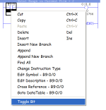
See picture below. To toggle a bit just right click on it , then click "Toggle Bit" to turn on or off.

toggleBit.PNG
 
If I toggle the bit like that (I just tried it again) it doesn't affect the output in the emulator. In the project I described above, both the latch and unlatch are high. I would expect that if I toggle input zero off and 1 on the unlatch would be high and the output would go low. That is how it performed in the real device.

On a side note, I've seen several times that people say to avoid latches. Why is that? Just that when the program gets long and complicated you might loose track of a latching input and have problems because of that?
 
Last edited:
Be aware that you debug files are special, and may not behave exactly like actual logic files. They are to be used for stuff you want not to be downloaded into a real processor, so they are very useful for writing logic to simulate the behavior of the machine when you are testing logic with only the emulator as a tool. The debug logic can do things like cause input temperature signals to rise only when output for Heater #1 is energized, or one second after SV210 is turned on, LS210a goes off, three seconds later LS210b turns on to simulate your actual control logic for a heater or a pneumatic cylinder.

Use and abuse of latches is covered well already, but learn to look at your simple control programs from the output device backwards as you program them. Ask yourself if a latch/unlatch pair is needed. Try to keep the latch and unlatch logic for the address together. When I have seen multiple latch and unlatch instructions that operate on the same address scattered all over the logic is has been a sign of bad form, and quirky code, but they can be used nicely and purposefully, just understand what they are needed for and when they can help you, not hurt you. I have seen logic that I believe was written by people who did not fully understand the scan cycle or seemed to be trying too hard to translate some style from the PC world semi-successfully.
 
Last edited:

Similar Topics

Hello all, The title explains what I need, how can I setup WinCC V14 and RSLogix Emulate500 so I can read/write values from the HMI to the PLC...
Replies
7
Views
3,003
Hi I deal with the micrologix series of PLCs on a weekly basis from the maintenance and operations side so thought I might have look whats going...
Replies
3
Views
1,772
I have an application I converted to FTSE 7.0, so far that is going fine. The programs written for in were written in RSLogix 500. I have the...
Replies
5
Views
2,696
Hi Everyone, I am not proficient in RSLogix 500 so I have a question regarding the evaluation of N7:0 data as an input. So as I understand in...
Replies
1
Views
79
Hi folks, in the alarm manager of Rslogix 5000, the tag-based alarm has been created. But when I tried to change the condition, it was found the...
Replies
2
Views
143
Back
Top Bottom