New and lost.

JIMCOO

Member
Join Date
Apr 2014
Location
va
Posts
13
Hi everyone, I'm new to PLC and everything it involves. I'm using LogicxPro simulator. I'm pretty much lost on how to write a document program using the I/) Simulator. I have no example how to write it in the Simulator. Here's the information:
1. When input A is closed, turn "on" and hold "on" outputs U and V until A opens.
2. When input A is closed and either B or C are open, turn "on" output W; otherwise, it should be "off."
3. When input D is closed or open, turn "on" output X.
4. When input D is closed, turn "on" output Y and turn "off" output Z.
A_I:1/0 B_I:1/1 C_I:1/2 DI:1/3 U_O:2/0 V_O:2/1 W_O:2/2 X_O:2/3
Y_O:2/4 Z_O:2/5
 
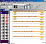
Here is how to get started. Some good documentation for this case is simply the descriptions of the 4 steps as shown in the attached picture. That explains very well when each output should go ON and OFF.

First start LogixPro, then select "Simulations, I/O Simulator". That brings up the screen on the left side of the picture below, giving access to the Input switches and Output indicators.

I have added all Outputs and done Step 1 for you. Now look at this example and add the Inputs on the correct rungs for the other 3 steps. Read the description of each step and figure out what combination of Inputs should make it happen. (As you add the other 3 Inputs B, C, and D, you should type in a symbol description for each PLC address). Then test to see if your deductions were correct. If not, try again.

New and Lost- Jimcoo.jpg
 
Last edited:
I/O Simulator

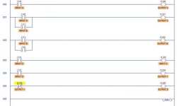
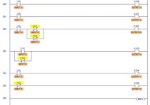
Thanks for the help in the right direction. I"m having to use a 10 inch acer laptop since LogicxPro won't work on my macbook. This is what I've come up with, not sure how much of it is correct. Thanks again.

LadderRungs.jpg
 
Add the rung comments as Lancie did. Copy and paste them into rung comments. I am not sure where to find rung comment entries in Logixpro, but someone else here will.

Anyway, you have a list of conditions for each output. Each output is defined once and only once in ladder logic, but some of the questions apply to more than one output in your test description. listing the outputs first as you have and following example by Lancie is good. Also, you have one of your output addresses commented as an input.

You have some mistakes, but if you put the questions as comments on each rung, you will be able to more easily see that you need an "or condition" or branch on at least one of them. You need to analyze and process each output definition written in your test question and break down the decision structure, look for key words like "or", "and" "when", "if" and be very extra careful with "not".

So once you have the outputs listed look at the question backwards "What are the conditions for output Z to be energized?" and do that for each output, answering based on the wording of the definitions in the written description.
 
Last edited:
I am not sure where to find rung comment entries in Logixpro, but someone else here will.
To add (or edit) a rung comment in LogixPro, place your mouse cursor over the rung number, then right-click, then select from the drop-down menu, "Edit Rung Comment".
2. When input A is closed and either B or C are open, turn "on" output W; otherwise, it should be "off."
The underlined bold words and, & or in statement #2 are clues to how to construct your Inputs to make it happen. In Boolean (binary) math, "AND" means that two or more bits are joined in a series construction like this for A and Not B:
|  Input A     Input B
|----| |---------|/|-------
|


"OR" means that bits are combined in a parallel construction like this for Not B or Not C:
|  Input A     Input B
|----| |----+----|/|-----+--
| | |
| | Input C |
| +----|/|-----+


Now the above ladder logic says: "If Input A AND (Not Input B OR Not Input C), then Do Something". For Statement #2, what is that "Something"?
 
Last edited:
Thanks for the reply. Its been awhile since I had to use the "AND" & "OR". Having to relearn it as I go. Its easier to understand when it is written out with a diagram to understand it.
>Now the above ladder logic says: "If Input A AND (Not Input B OR Not Input C), then Do Something". For Statement #2, what is that "Something"?<

The something would be: they are open, turn on Output W.

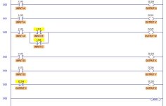
LadderRungs1.jpg
 
The complete ladder logic statement of Rung 003 would be:
"If Input A AND (Not Input B OR Not Input C), then Output W."

In Boolean terms, Output W = Input A AND (Not Input B OR Not Input C).

Okay, now you have completed statements 1 and 2. What about 3 "when D is closed or open"? The OR should tip you off that a parallel branch is needed. But each branch uses the same Input D, except that the top branch is looking to see if Input D is Closed (binary 1), and the bottom branch is looking to see if D is Open (binary 0). Because there are only 2 possible states, then this parallel OR branch would cover all possible conditions of Input D.

.....how to write a documented program using the I/O Simulator.
Do not forget about that little DOCUMENTed requirement. As your program stands now, it deserves a Fail grade for not following instructions about providing documentation for each rung. All you need to do is Copy, go to Edit Comment mode, and then Paste, as I did for the program in my post #2.

Remember that the great advantage of LogixPro is that you do not have to wonder if your logic is correct. Simply (1) Download the program to the PLC (simulated PLC), (2) Switch to Online Mode, (3) Switch from Program to Run mode. Now when you press a switch, you can see what happens to each output.

PS: Your Rung 005, although it may work, does not use the same terms as your Statement #4. In other words, for this specific problem, you should define your Outputs in terms of Inputs, not other Outputs.
 
Last edited:
I/O Simulator

Hopefully this corrects the mistakes I've made. I changed Rung 005 to a "NOT" INPUT D.

LadderRungs2.jpg
 
Good job. It looks almost correct to me. You still have O:2/4 labelled as INPUT D. Logically it is correct though, and I would accept your earlier version for output Z as well. Notice that rung three will always evaluate to true, so further simplification could make it an unconditional output. No matter whether there is a one or a zero in bit box I:1/3, we are turning on Output X, so as long as the processor is in RUN mode then...

Your code as written would grade 100% I do believe after you fix that address comment. So, technically, your only mistake earlier was on rung 3, you needed Output X to always be on one way or uther. I personally, would make comments always a part of your grade.
 
Last edited:
Here is the corrected version. Thank you guys for the tips. Hopefully I'll be able to help others on this site also.

LadderRungs2.jpg
 
I personally, would make comments always a part of your grade.
I agree. They were put in, then removed in the final version. Why is "comments are important" so hard for students to understand?
                F

 
I/O Simulator

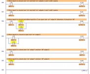
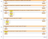
Actually I have two versions. One with the comments and one without. For here I mistakenly posted the one without comments. Here is the other version with the comments:

LadderRungs3.jpg
 
I/O Simulator

I also agree, comments should be included. I want to thank you guys again for your insight and expertise. I will look into how I can use Logicxpro on my macbook to make it easier for me to use. When I received the textbooks and the cd there was very brief instructions on how to use Logicxpro. I definitely have more to learn. Thanks.
 
I will look into how I can use Logixpro on my macbook to make it easier for me to use.
You will need software to convert your Mac to a Virtual IBM PC. See this quote from theLearningPit.com
The CD/Key is not compatible with Mac computers, or computers running unix/linux. Mac computers running Virtual PC (W95) software can usually be unlocked however with LogixPro's normal software user keys.
 

Similar Topics

hi everyone, I have a problem, it seems that in somewhere on the programming the reference tends to lost mabye one time at day. I write this...
Replies
0
Views
78
Well, not sure what else we can do with this one at the moment. Will chat with Rockwell in the morning but am not expecting much. Guess I'm...
Replies
6
Views
1,117
When E300 powered off, the ethernet device tag data stayed at last know state, for example, fault bit is still Off, ready bit is still ON, status...
Replies
8
Views
1,004
I'm working with a 1734-AENT PointIO module (manual) connected to a 1769-L30ER controller over fiber ethernet. The 1734 PointIO module has some...
Replies
3
Views
1,045
Hello, My laptop was rebooted lost 500 & 5000 tried to re-install but need to activate, need help badly, Thanks
Replies
1
Views
773
Back
Top Bottom